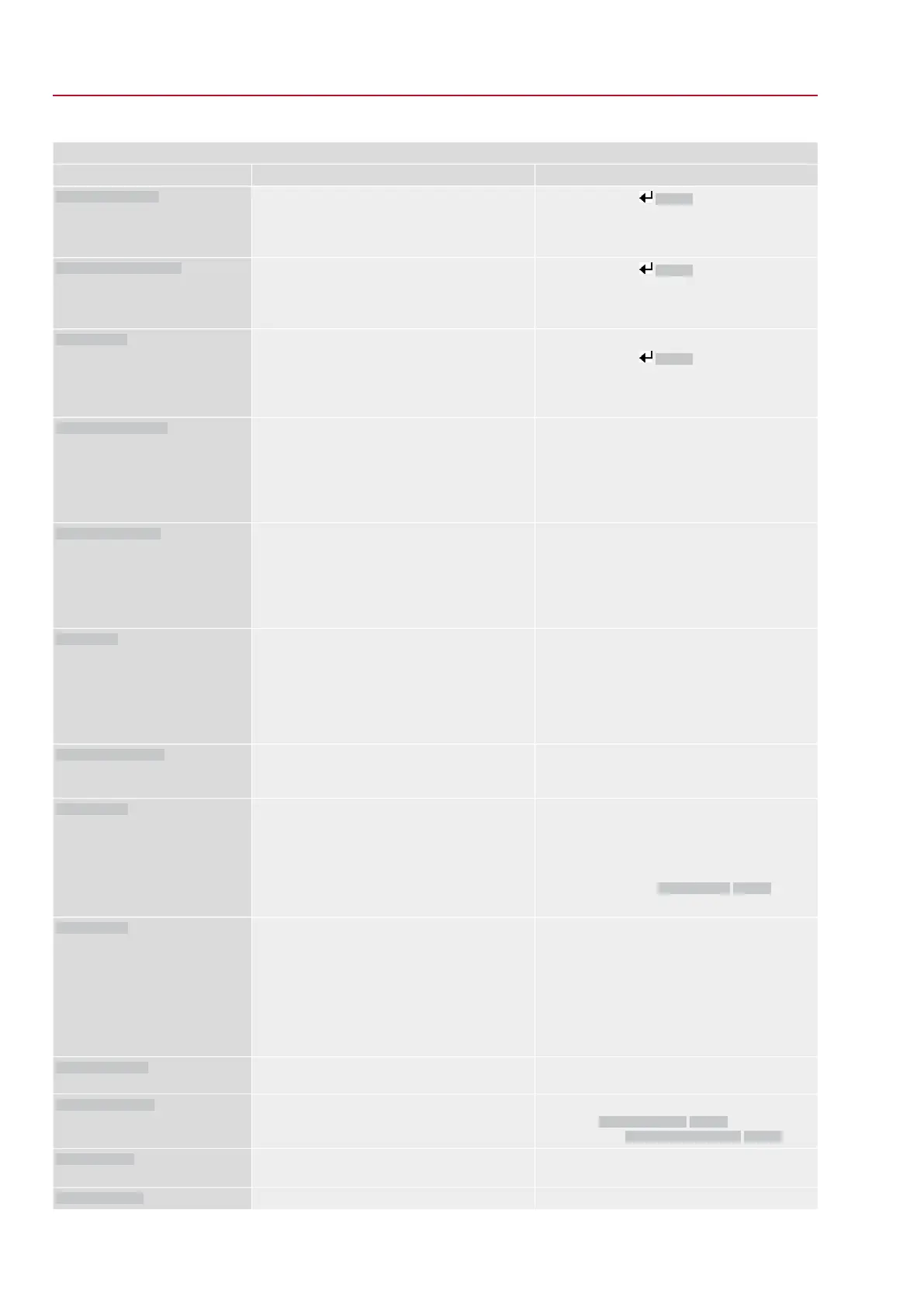
Table 30:
Faults and Failure
RemedyDescription/causeIndication on display
Press push button Details to display a list of indi-
vidual indications.
For a description of the individual signals, refer to
Manual (Operation and setting).
Collective signal 11:
Configuration error has occurred.
Configuration error
Press push button Details to display a list of indi-
vidual indications.
For a description of the individual signals, refer to
Manual (Operation and setting).
Collective signal 22:
Configuration error has occurred.
Config. error REMOTE
AUMA service
Press push button Details to display a list of indi-
vidual indications.
For a description of the individual signals, refer to
Manual (Operation and setting).
Collective signal 14:
Internal error has occurred.
Internal error
Perform one of the following measures:
●
Issue operation command in direction OPEN.
●
Set selector switch to position Local control
(LOCAL) and reset fault indication via push
button RESET.
●
Execute reset command via fieldbus.
Torque fault in direction CLOSE
Torque fault CLOSE
Perform one of the following measures:
●
Issue operation command in direction CLOSE.
●
Set selector switch to position Local control
(LOCAL) and reset fault indication via push
button RESET.
●
Execute reset command via fieldbus.
Torque fault in direction OPEN
Torque fault OPEN
Test/connect phases.
●
When connecting to a 3-ph AC system and with
internal 24 V DC supply of the electronics:
Phase 2 is missing.
●
When connecting to a 3-ph or 1-ph AC system
and with external 24 V DC supply of the elec-
tronics: One of the phases L1, L2 or L3 is
missing.
Phase fault
Correct the sequence of the phase conductors L1,
L2 and L3 by exchanging two phases.
The phase conductors L1, L2 and L3 are connected
in the wrong sequence.
Only applicable if connected to a 3-ph AC system.
Incorrect phase seq
●
Check mains voltage.
For 3-phase/1-phase AC current, the permiss-
ible variation of the mains voltage is ±10 %
(option ±30 %).The permissible variation of the
mains voltage is ±5 %
●
Check parameter Tripping time M0172, extend
time frame if required.
Due to insufficient mains quality, the controls cannot
detect the phase sequence (sequence of phase
conductors L1, L2 and L3) within the pre-set time
frame provided for monitoring.
Mains quality
●
Cool down, wait.
●
If the fault indication display persists after cool-
ing down:
-
Set selector switch to position Local con-
trol (LOCAL) and reset fault indication via
push button RESET.
-
Execute reset command via fieldbus.
●
Check fuses.
Motor protection tripped
Thermal fault
Check movement at actuator.No actuator reaction to operation commands within
the set reaction time.
Fault no reaction
Check device configuration:
Parameter Low limit Uspan M0832 must be less
than parameter Volt.level diff. potent. M0833.
Potentiometer is outside the permissible range.
Poti Out of Range
LPV: Lift Plug Valve function
The master actuator signals a fault
LPV not ready
1)
Check wiring.Loss of signal analogue input 1
Wrn input AIN 1
68
SQ 05.2 – SQ 14.2 / SQR 05.2 – SQR 14.2 Control unit - electromechanical
Corrective action AC 01.2 Intrusive Modbus RTU

 Loading...


