6.3.2. Cable connection
Table 17:
Terminal cross sections and tightening torques
Connection typeTerminal cross sectionsDesignation
Screw-type terminals
Tightening torque =
1.2 – 1.5 Nm
Flexible or solid:
0.25 – 10.0 mm
2
(for one wire per terminal)
Flexible:
2 x 0.25 – 4 mm
2
(for two wires per terminal)
Power contacts
(U1, V1, W1, U2, V2, W2)
PE connection
Spring clamp terminalsFlexible or solid:
0.25 – 2.5 mm
2
(for one wire per terminal)
2 x 0.25 – 0.75 mm
2
(for two wires per termin-
al)
Control contacts
(1 to 36, 37 to 50)
Ring lug/U-bracket
Tightening torque = 3 – 4
Nm
2 x M6 for cables with M6 ring lug or with U-
bracket for up to two wires with
1.5 mm
2
– 10 mm
2
Protective earth connection
within frame (customer connec-
tion)
Procedure
1. Remove cable sheathing in a length of 250 – 300 mm.
2. Insert the wires into the cable glands.
3. Fasten cable glands with the specified torque to ensure required enclosure
protection.
Information: For shielded cables: Link the cable shield end via the cable gland
to the housing (earthing).
4. Strip wires:
4.1 Remove wire sheathing of control cables (1...50) in a length of approx. 10
mm
4.2 Remove wire sheathing of motor cables (U, V, W) in a length of approx.
12 mm
5. Connect cables according to order-related wiring diagram.
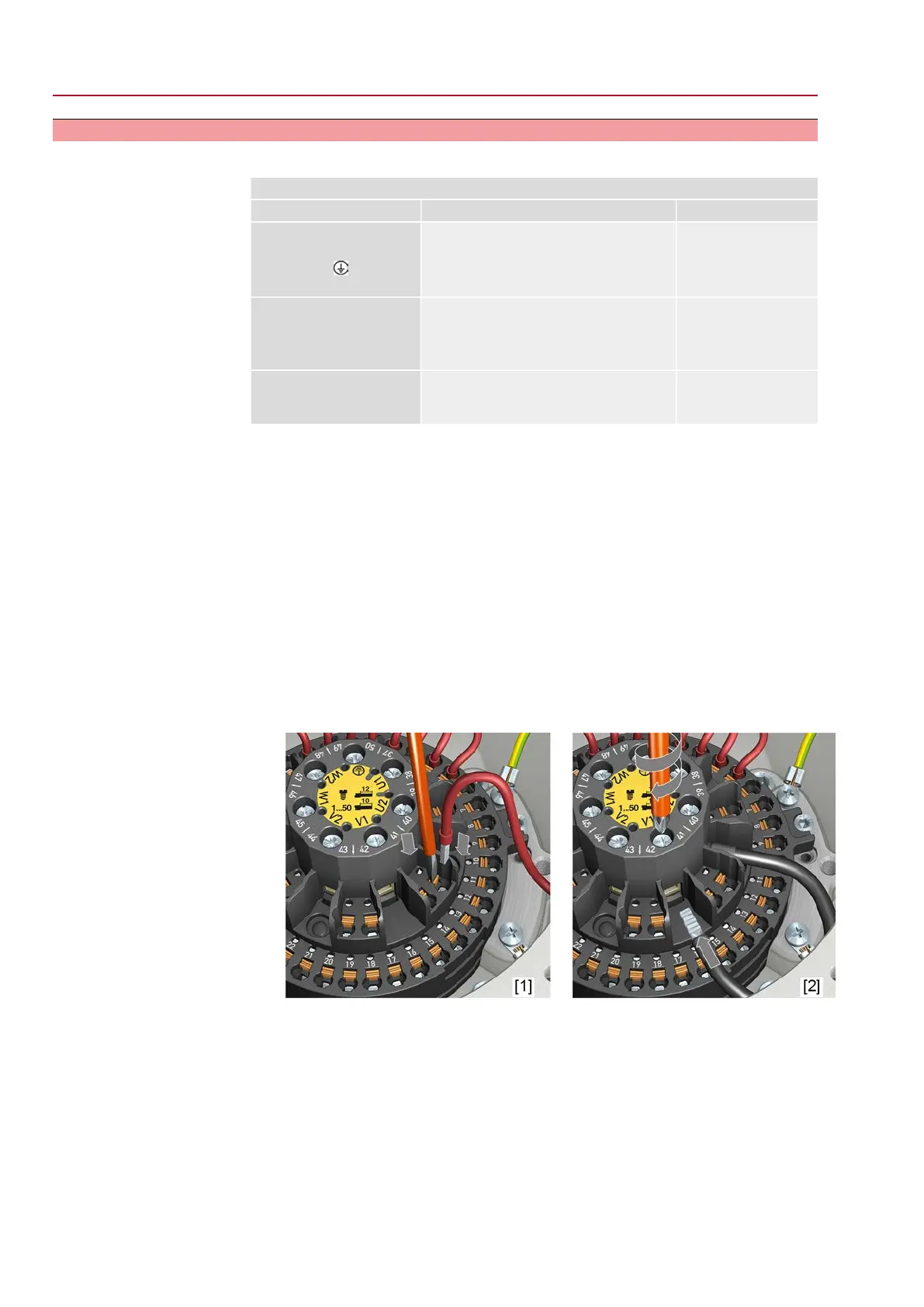
Figure 21: Connect cables to terminal carrier
[1] Fitting control cables into spring clamp terminals
[2] Tightening power terminals
Information
For service purposes, each spring clamp terminal is equipped with a test contact
located above the numbering.
Information
For flexible cables: for screw-type terminals, use wire end sleeves according to DIN
46228. For spring clamp terminals, connection is possible without wire end sleeves.
28
SQEx 05.2 – SQEx 14.2/SQREx 05.2 – SQREx 14.2 Control unit: electronic (MWG)
Electrical connection ACExC 01.2 Non-Intrusive Profibus DP