E. Powe
1. Connect the p
supply will lig
h
supplyfromth
2. Connect the o
u
polarity andus
3. Connect the po
during which t
The message“
bedisplayed.
5-EN
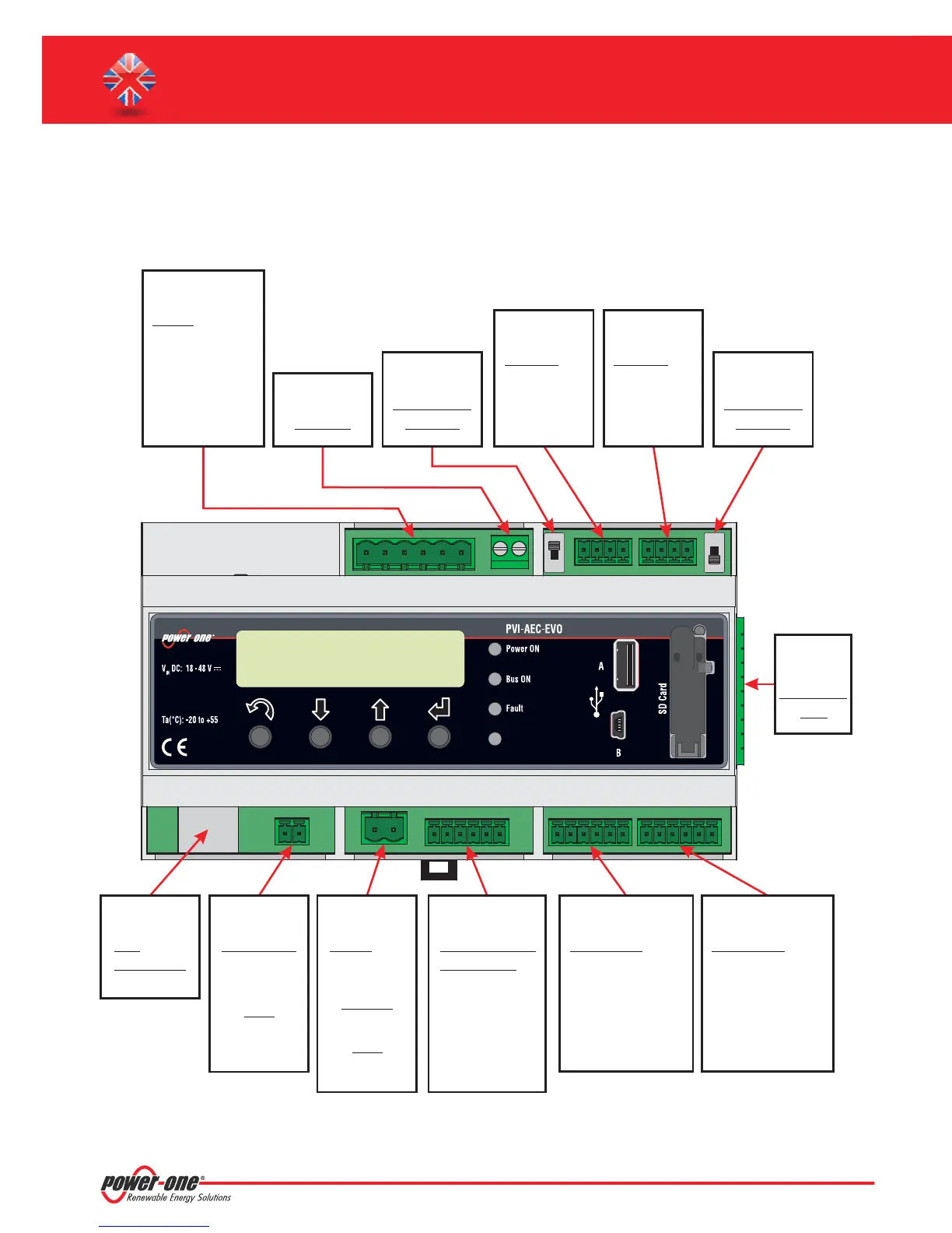
D. Pin-Out of System Connectors
Thediagrambelowshowsthepin-outoftheconnectorswhichallowthesystemconnection.
L(+)
PVI-AEC-EVO / PVI-AEC-EVO LIGHT
QUICK INSTALLATION GUIDE
* In the PVI-AEC-EVO LIGHT model the RS458/1 port (J17) is not available as inverter communication port,but can be used only to
acquireparametersfrom powermetersequippedwithModbuscommunicationinterface.ISKRAEMECO
Note: The sy
confo
J18
BATTERY IN
1) + Batt.
2) - Batt.
J7
LAN
IEEE802.3u
J8
Vin DC
1) + Vcc
2) - Vcc
J3
ANALOG INPUT
PT100/1000
1) PT_ALIM
2) PT_SENSE
3) PT_RTN
4) AIn_RTN
5) AIn 1
6) AIn 2
J20
DIGITAL I/O
1) DO_RTN_PWM1
2) DO_ _PWM2
3) DO_PWM 1
4) DO_PWM 2
5) DIn 1
6) DIn_RTN
RTN
J4
DIGITAL I/O
1) DIn 2
2) DIn 3
3) DIn 4
4) DIn_RTN
5) DIn 5 / CONT 2
6) DIn 6 / CONT 1
11122
3
4
5
6
123456 1234562
123456
12
3
4
1234
J12
GROUND
J17
RS485/1
1) RTN
2) - T/R
3) +T/R
4) +5V
*
J5
RELAY
1) RELAY1-C
2) RELAY 1 - N.O
3)
4)
5)
6)
RELAY2-C
RELAY 2 - N.O
RELAY3-C
RELAY 3 - N.O
J15
RS485/2
1) RTN
2) - T/R
3) +T/R
4) +5V
S2
120
RS485/1
Ω TERM.
S1
120
RS485/2
Ω TERM.
J9
EXPANSION
BUS
NOTE:
Only for dedicated
accessory
PVI-BATTERY-PACK
INPUT DC:
24 Vdc
0,3 A
(max. 48 Vdc)
NOTE:
Use the provided
power supply