Note: The m
conne
than6
them
In the
string
variat
PVI-3.
PVI-1
Note: When
towir
Thela
the12
string
Note: In cas
RS485
Note: For fu
resist
Note: All str
contin
For si
indica
7-EN
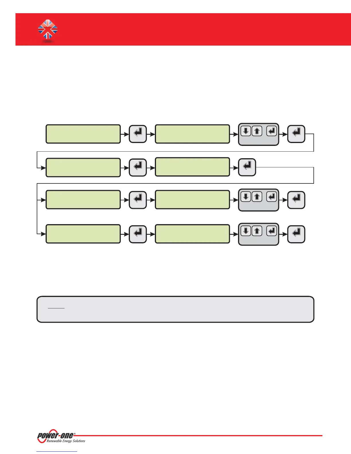
F. Date and time settings
1. Enterthemain menuas administrator(Seepar.'C’).
2. Access the menu and then select the sub-menu. This enables to set the
correctdatein the system.
3. Return tothe menu and then select the sub-menu. This enables toset the correct time
inthe system.
'SET TINGS' > 'DATALOGGER' 'SET DATE'
'DATALOGGER' 'SET TIME'
>datalogger
io settings
>settings
change password
ENTER
ENTER
PVI-AEC-EVO ......
12.00.00 01/01/11
menu pin
0***
ENTER ENTER
>set date
set time
>set date
01/01/11
ENTER
ENTER
>set time
network
>set time
12.00.00
ENTER ENTER
CHANGE VALUE
NEXT
FIELD
CHANGE VALUE
NEXT
FIELD
CHANGE VALUE
NEXT
DIGIT
SET PIN TO 0010
G. Connection of the RS485 line and inverter acquisition
check
Theconnection oftheRS485 linemust becarried outrespectingthe pin-outsof theJ15 and/orJ17connectors.
I
t is recommended to connect the RS485 line when all the equipment is switched off (both the monitoring system
andthe inverters)and tostartupthe monitoringsystemfirst andthen the inverters. It isrecommendedto:
Use a cable for RS485 applications with the following characteristics: 1 twisted pair+1conductor or two
twisted pairs,Screen and characteristic Impedance equal to 120 . For further information on the cable to be
usedrefertoAppendix 2.
Makesurethesignals correspond.
Makesurethatall threelines (+T/R,-T/Rand RTN)areconnectedaccordingto thediagramsin pages9-10.
Make sure that each element in the chain (each inverter or each 55kW module) has a RS485 address that is
differentfrom theothers.This addresscan beset viathe display oftheinverter.
Ω
l
l
l
l
l
Makesurethatthe communicationline screenisgroundedaccordingtothe diagramsin pages9- 10).
Note: For PVI-AEC-EVO LIGHT, the only usable RS485 port for inverter monitoring is the RS485/2,
correspondenttoconnectorJ15.
Note: For P
addr
e
PVI-AEC-EVO / PVI-AEC-EVO LIGHT
QUICK INSTALLATION GUIDE
Note: The ce
with“
line in
theca