Page 23 of 51
5.3.3 ASSOCIATION (or CONFIGURATION) OF ADDITIONAL INVERTERS
Whenever deemed necessary to add one or more inverters please procede as follows :
• Check that all inverters are switched on and disassociate all already configured inverters as per the
guided procedure described in paragraph 5.3.2.
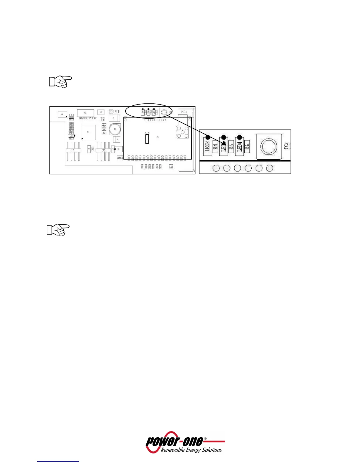
NOTE: When the radio connection is chosen as communication mean (by means of inverter
PVI-RADIOMODULE installed within the inverters), verify the effective disassociation of the
radio moduli by checking the orange LED light (LED 3 in figure 10) which must be flashing.
Figure 10 – LED 3 (orange) position on PVI-RADIOMODULE
• Repeat the inverter association procedure, by inserting the new inverter number to be searched
during the scanning phase as described in paragraph 5.3.1.
NOTE: please remember that inverter scanning is based on the RS485 address (independently
from the chosen communication type, radio or RS485). When multi-inverter installation is
required, they must have different RS485 addresses to enable recognition from the system.
5.4 BASIC DEVICE SETTING
5.4.1 BRIGHTNESS
Backlight setting is carried out from the SETTING menu and then “Display” must be selected. At this point
use the + o – touchscreen keys to set the brightness.
5.4.2 LANGUAGE
Menu language setting is carried out through the SETTING menu by selecting “language”. At this point
language selection is possible.
5.4.3 ENERGY SAVING MODALITY (STAND BY or “SLEEP MODE”)
Stand by or sleep mode can be activated after a certain period of time which can be set from the SETTING
Menu selecting “Stand by / Sleep mode”, to achieve a longer battery duration. At this point energy saving
mode can be activated as well as the length of inactivity time after which the stand by / sleeping mode is
on.
 Loading...