Page 26 of 51
5.7 MAIN MENU
NOTE: because of the continuous firmware updates, the graphics may be slightly different from
the pictures shown below. This does not constitute a product non-conformity.
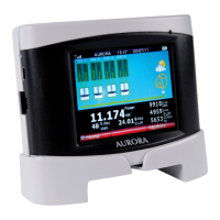
5.7.1 DEFAULT SCREEN
The PVI-DESKTOP remains, by default, on an intuitive screen, summarizing the system's important data and
operating status. The screen is shown in the figure below.
Each inverter in the system is surrounded by a line indicating different states:
• Green line – Inverter connected and running correctly
• Yellow line – Inverter not connected to the network
• Red line – Inverter in alarm
• Blue line – Inverter off or no radio or wired communication
Touching or clicking on each inverter a bubble showing the recognition data for the individual inverter and
its operating status can be seen.
The top bar contains the information regarding date and time, battery status (three bars mean fully
charged battery), the power of the radio signal received (three bars mean full strength radio signal) and
the radio communication icon.
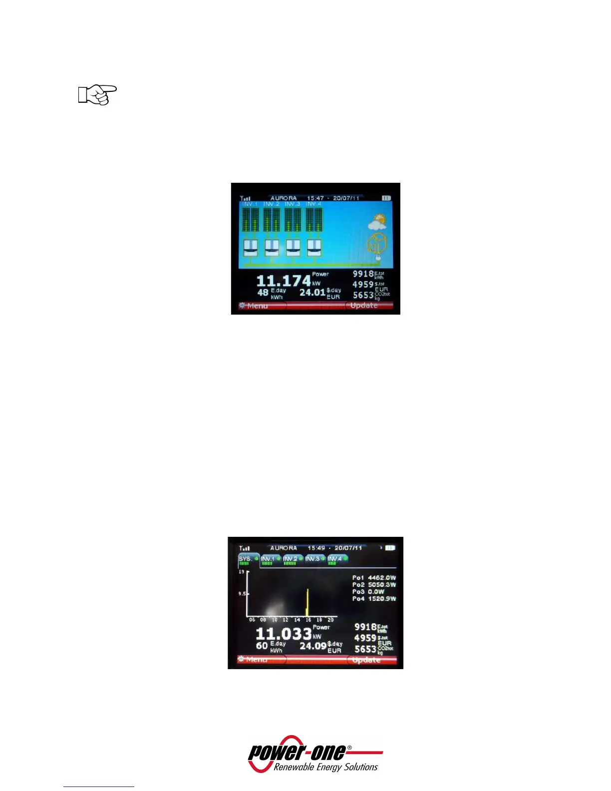
The central black band shows the summary data for the whole system. Touching or clicking any point of
the black band gives a detailed view of the system. The screen that opens is detailed in the following
figure.
 Loading...