Page 12 of 51
2.5.1 POWER SUPPLY CONNECTOR
Component 10 in Figure 6 shows the input connector for the power-supply on the back of the device.
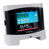
Figure 7 shows power-supply polarity.
Figure 7 – Power-supply polarity
WARNING: use the provided power-supply to power the device.
2.5.2 USB CONNECTOR
Component 8 in Figure 6 shows the USB 2.0 interface connector.
The connector is a USB mini B and is used with the cable supplied.
The interface is designed to connect the device to a standard PC with a USB 2.0 port.
Insertion of other types of peripheral such as mass storage keys, external hard disks, mobile
telephones, MP3 players and other devices is not permitted.
Communication with the PC occurs after installation of the special drivers and through the software on the
CD attached to the packaging.
The USB connector can also be used to recharge the PVI-DESKTOP (please refer to paragraph 5.1).
2.5.3 RS485 CONNECTOR
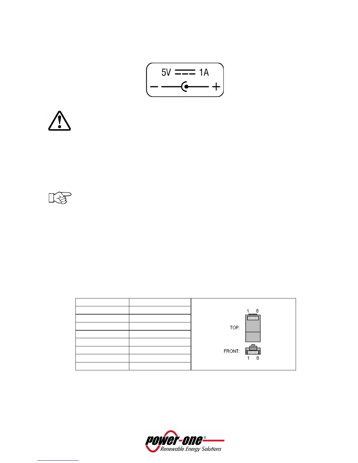
Component 7 in Figure 6 shows the connector entry of the RS485 port. This port is to be used exclusively
for Aurora inverters connection. The connecting cables must have a RJ45 connector with 8 pins and must
be used in accordance to the following table.
Pin N° Function
1 not used
2 not used
3 +T/R
4 not used
5 -T/R
6 not used
7 GND
8 not used
This connection is as an alternative to the radio communication with the inverters.
 Loading...