Page 11 of 51
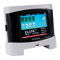
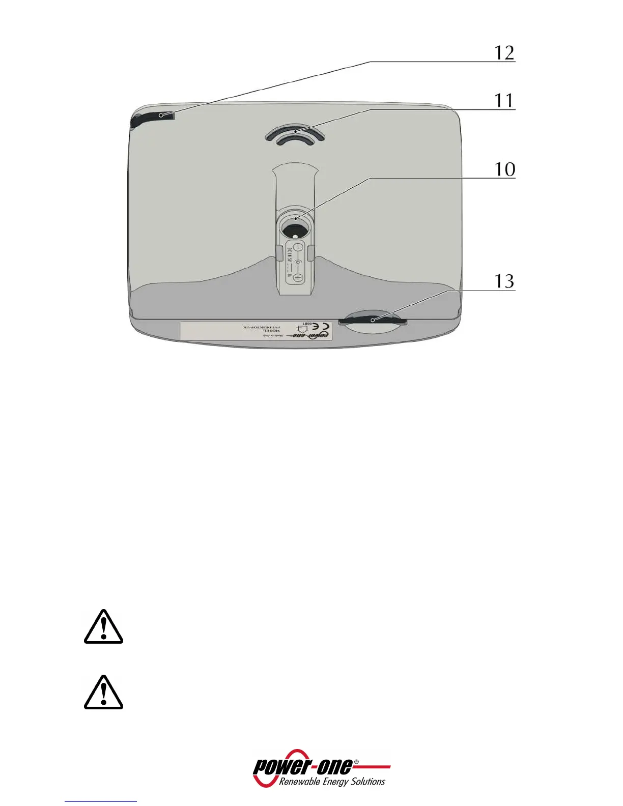
Figure 6 - Components position
1. PVI-DESKTOP
2. Docking station
3. Holes for wall mounting
4. Touch screen display
5. Multicolour LED status indicator
6. Switch ON/OFF button
7. RS485 communication port
8. USB 2.0 communication port
9. Reset button (inner)
10. Power-supply input
11. Sound output holes
12. Stylus Pen groove
13. SD card connector
WARNING: Component 7. is a connector to be used solely and exclusively for connection by
RS485 to the Aurora inverters. On no account use it for anything else (i.e. connection of
Ethernet cables for PC or phone connections) to prevent damage to the communication port.
WARNING: the PVI-DESKTOP is fitted with security labels which, if removed or showing scratch
marks, make the warranty null and void. Maintenance operations and components
replacement on the PVI-DESKTOP can only be carried out by qualified specialist staff.
 Loading...