Page 41 of 51
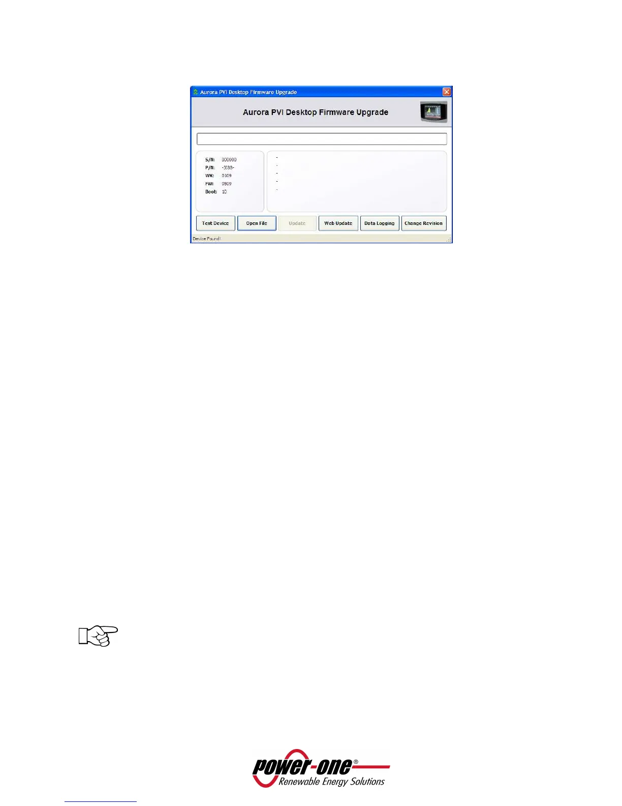
• To update the PVI-DESKTOP using the Aurora Communicator, choose Open File from the next screen
and then select Update.
6.3.2 FIRMWARE UPGRADE VIA SD CARD
This update procedure presupposes availability of FW (previously downloaded from Power-One server)
and to be able to directly interact using the SD Card memory (SD card reader).
• Disassociate the inverters following procedure described in paragraph 5.3.2
• Turn off the PVI-DESKTOP by pressing the ON/OFF key for more than 5 seconds and confirming
the action on the display.
• Take the SD card out of the PVI-DESKTOP by pressing it lightly.
• Insert the SD card into a reader connected to the PC or into the SD card slot.
• Delete SYSTEM and SNxxxxxx folders (if necessary carry out a PC back-up).
• If the folder 'BOOT' does not exist, create it and rename it as BOOT; copy the file containing the
new FW rename it as boot.ben.
• Remove the SD card reader from the PC following the safe hardware removal procedure or take
the SD card out of the slot and put it back in the PVI-DESKTOP.
• Switch the PVI-DESKTOP System on.
• Carry out the configuration procedure WITHOUT scanning. When asked “Scanning now” select
“NOT NOW”.
• Access “FW Settings-Upgrade” and follow the indications on the display to start the FW update.
• Once the new software has been read and loaded, a selection dialogue will appear on the
screen. From this screen it is possible to decide whether to install the new firmware, return to
the previous version or cancel the procedure and keep the current firmware.
• Wait until the PVI-DESKTOP concludes the installation operations to see the menu automatically
reappearing.
NOTE: some minutes are required to end the procedure, after which the screen will show
“Boot…”. This screen is totally normal and represents system restart following the FW update.
• From the “Firmware-Information” menu verify that the FW version in progress is the desired one.
• Access the “Settings-Wizard” menu and configure the system following the guided procedure.
Complete the configuration by associating the inverters to the system (see paragraph 5.3).
 Loading...