D 900 AP / D 1000 AP / D 1000 APG
37
(fi g. 3) (fi g. 2) (fi g. 1)(fi g. 4)
Periodic
maintenance
operations
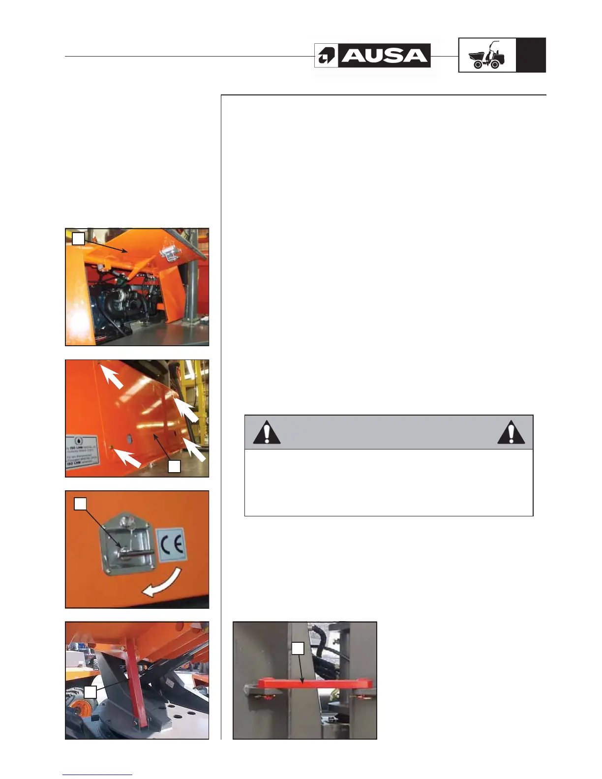
Access for maintenance (fig. 1, 2, 3)
The engine, the transmission and the filters are located under the side covers at the
rear of the machine (fig. 1) and underneath the maintenance access panel, located
to the side of the operator’s seat. (fig. 2). In order to access them you must follow this
process:
a. Engine cover
b. Maintenance access panel
c. Engine cover locks
To lift the side covers, lift the lock and turn it to the right (fig. 3). Lift the cover (right or
left) by pulling it. There are gas springs which compensate the weight and hold it in the
elevated position.
To access the maintenance access panel, unscrew the fixing screws and remove the
cover.
Lock to avoid the descent of the cargo box (fig. 4)
There is a prop to avoid the lifted bucket box from descending when maintenance
operations are being carried out.
d. Lifted bucket prop
This ensures that you work on the machine in complete safety.
Chassis articulation linking bar (fig. 5)
Before carrying out any intervention which requires you to be located between the two
parts of the chassis, immobilise the articulation with the linking bar provided for this
purpose.
e. Chassis articulation linking bar
WARNING
Should removal of a fixing device (lock tabs, self locking fasteners, etc) be
required to carry out disassembly / assembly, always replace with a new one.
Initial maintenance is very important and must not be neglected. See the
MAINTENANCE CHART in this Manual. The maintenance of some of the
components can be carried out by the clients if they wish to do so.
Other operations must be carried out by an authorised AUSA dealer.
(fi g. 5)
a
b
c
d
e


 To Next Page