OM-270 231 Page 12
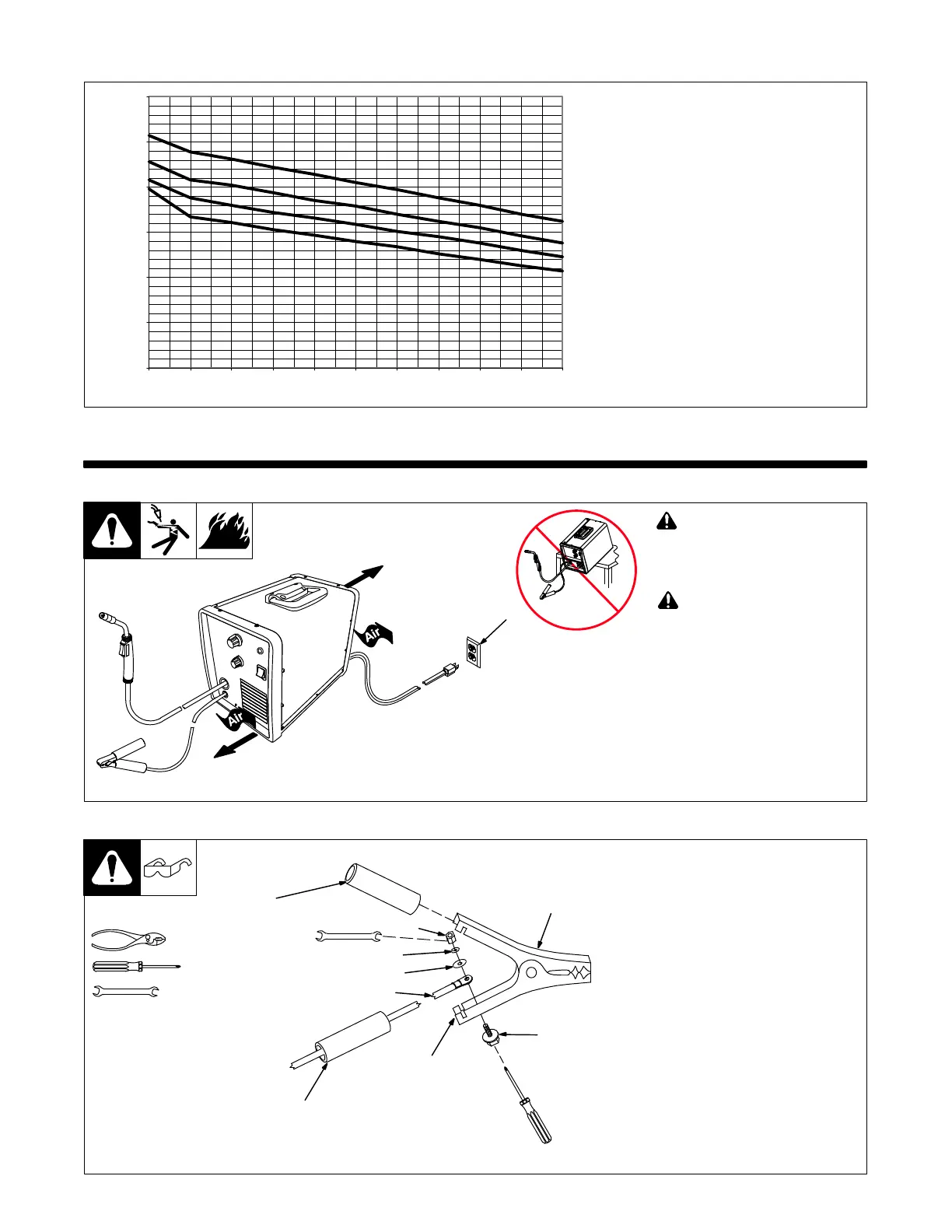
4-4. Volt-Ampere Curves
The volt-ampere curves show the
voltage and amperage output capa-
bilities of the welding power source.
270 507-A
Voltage
Amperage
0
5
10
15
20
25
30
0 102030405060708090100
Range 4
Range 2
Range 3
Range 1
SECTION 5 − INSTALLATION
5-1. Selecting A Location
! Special installation may be
required where gasoline or
volatile liquids are present −
see NEC Article 511 or CEC
Section 20.
! Do not move or operate unit
where it could tip.
1 Grounded Receptacle
Locate unit near correct input
power supply.
161-062
18 in.
(460 mm)
18 in.
(460 mm)
1
5-2. Installing Work Clamp
. Connection hardware must be tight-
ened with proper tools. Do not just
hand tighten hardware. A loose
electrical connection will cause
poor weld performance and exces-
sive heating of the work clamp.
1 Work Clamp
2 Work Cable From Unit
3 Insulator Grip
Slide one insulating grip over work cable
before connecting to clamp.
4 Nut
5 Lock Washer
6 Flat Washer
7 Screw
8 Work Clamp Tabs
Bend tabs around work cable.
Slide insulating grips over handles.
Ref. 802 456
4
2
1
7
8
Tools Needed:
10 mm
3
5
6
3