OM-270 231 Page 16
SECTION 6 − OPERATION
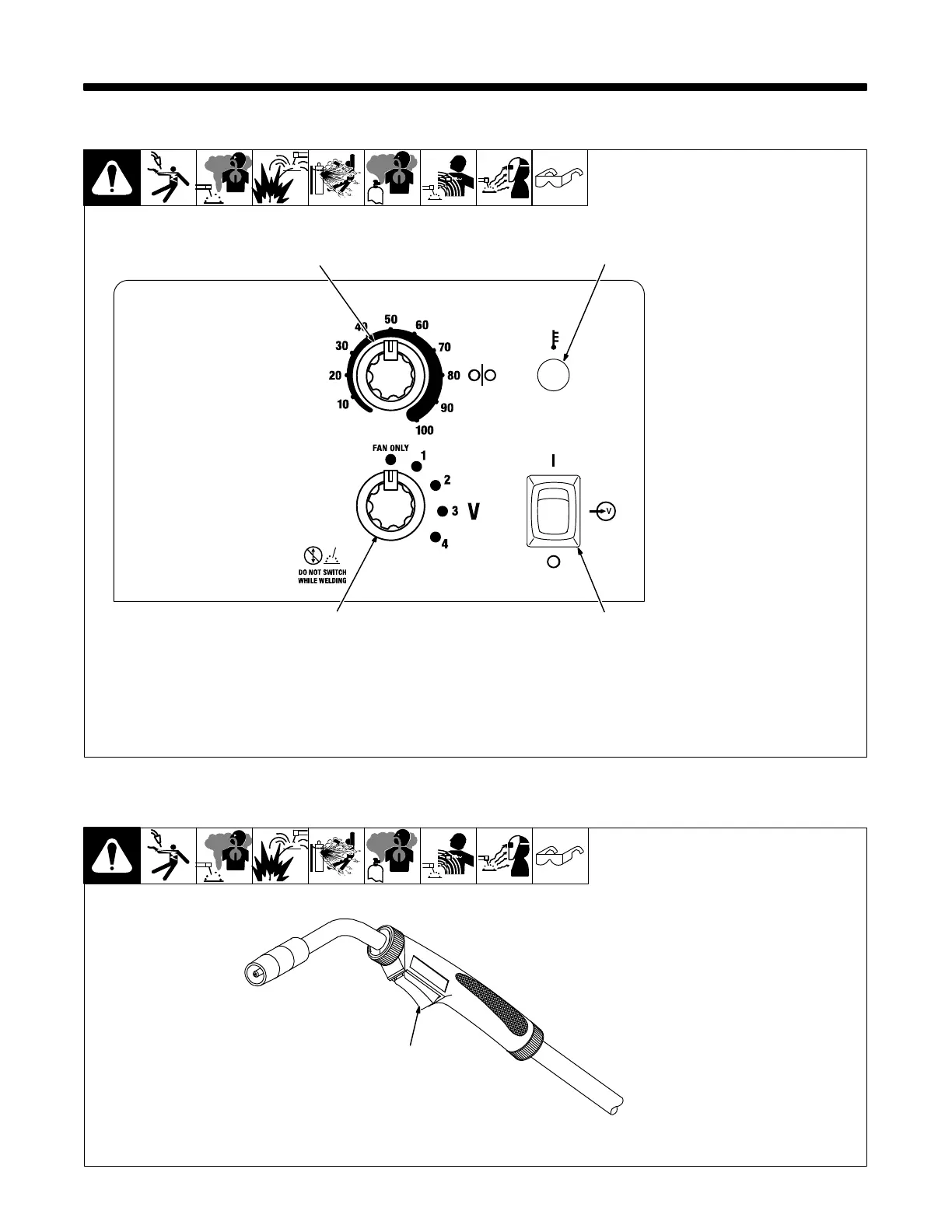
6-1. Controls
1 Voltage Switch
NOTICE − Do not switch under
load.
Use control to select the weld
voltage range. As the thickness of
material increases, a higher voltage
range must be selected (see weld
setting label in welding power
source or in Section 6-3).
When Voltage switch is placed in
the Fan Only position there is no
weld output and wire does not feed.
. Switch must “click” into detent
position for weld output.
2 Wire Feed Control
Use control to select a wire feed
speed. See weld setting label in
welding power source or in Section
6-3.
3 Power Switch
Use switch to turn unit on and off.
4 Over Temperature Light
If unit overheats, light turns on and
output stops. Allow unit to cool be-
fore attempting to weld.
Light goes out when unit has cooled
and welding can resume.
Ref. 229 999-A
1
2
3
4
6-2. Operating The Gun
Ref. 804 240-A
1 Trigger Switch
Press and hold gun trigger to ener-
gize wire feed motor and begin
welding. Gun trigger must be
pressed (closed) and held for weld-
ing to begin.
Release the gun trigger to stop weld
output and wire feed.
1