16 | P a g e
Additional Frames Connection
1. Using a utilities dolly, position the frames per the site plan
2. Ensure power is OFF at the UPS
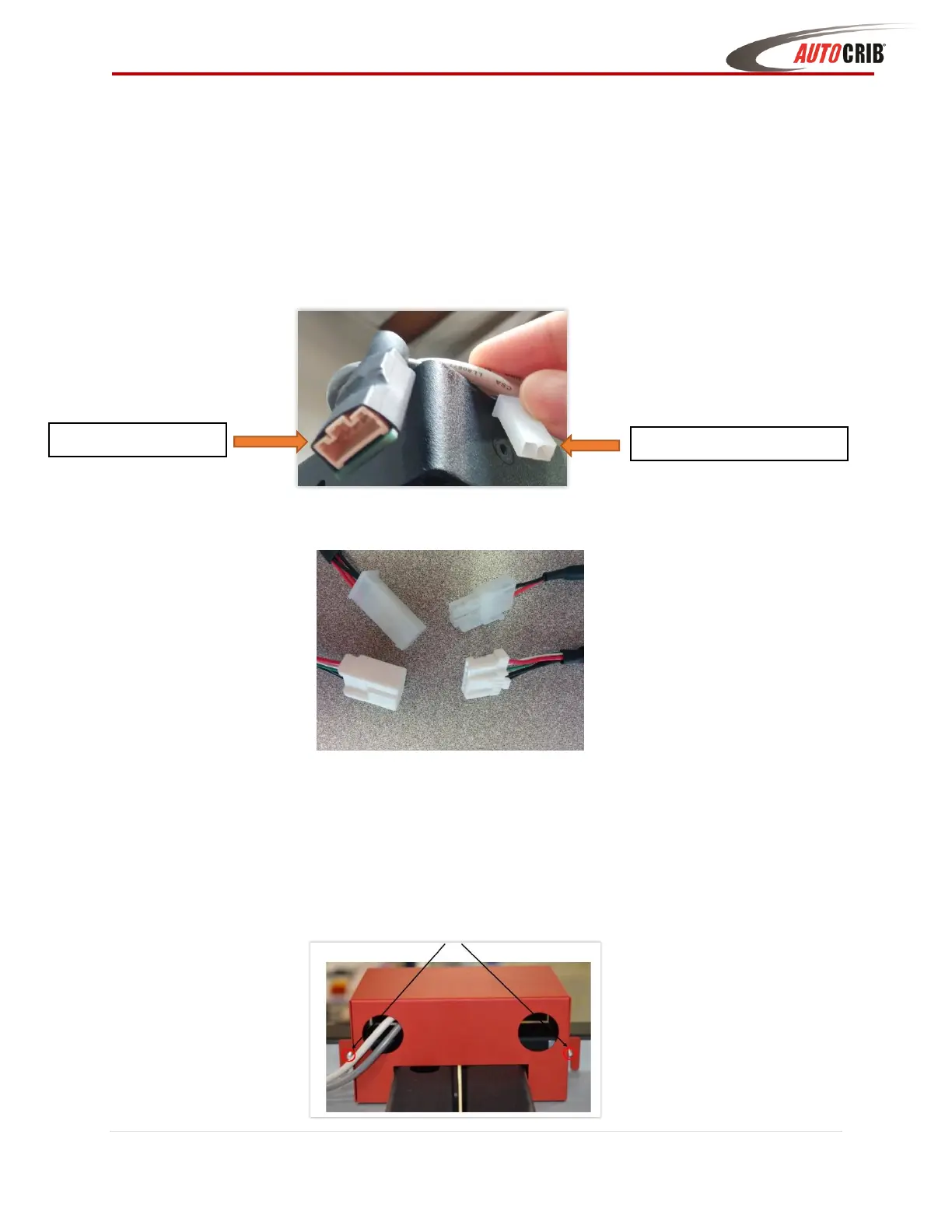
3. Pull the ends of the DC Power & Data cables out of both adjoining frames
4. Connect the male power and hirose cables to the female power and hirose connectors
5. Turn on power at UPS - Internal LED strips should light up, and LEDs on the distribution
and latch boards should light up (Blue LED Blinking on the board = board is powered &
communicating with CBI controller)
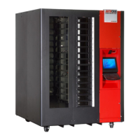
6. Place the red backbone cover over the wiring connections, spanning the two frame
corners (Align the slots on the cover to the studs on the frame and tighten nuts)