© 2001 Directed Electronics, Inc. Vista, CA 25
on-board doubleguard shock sensor
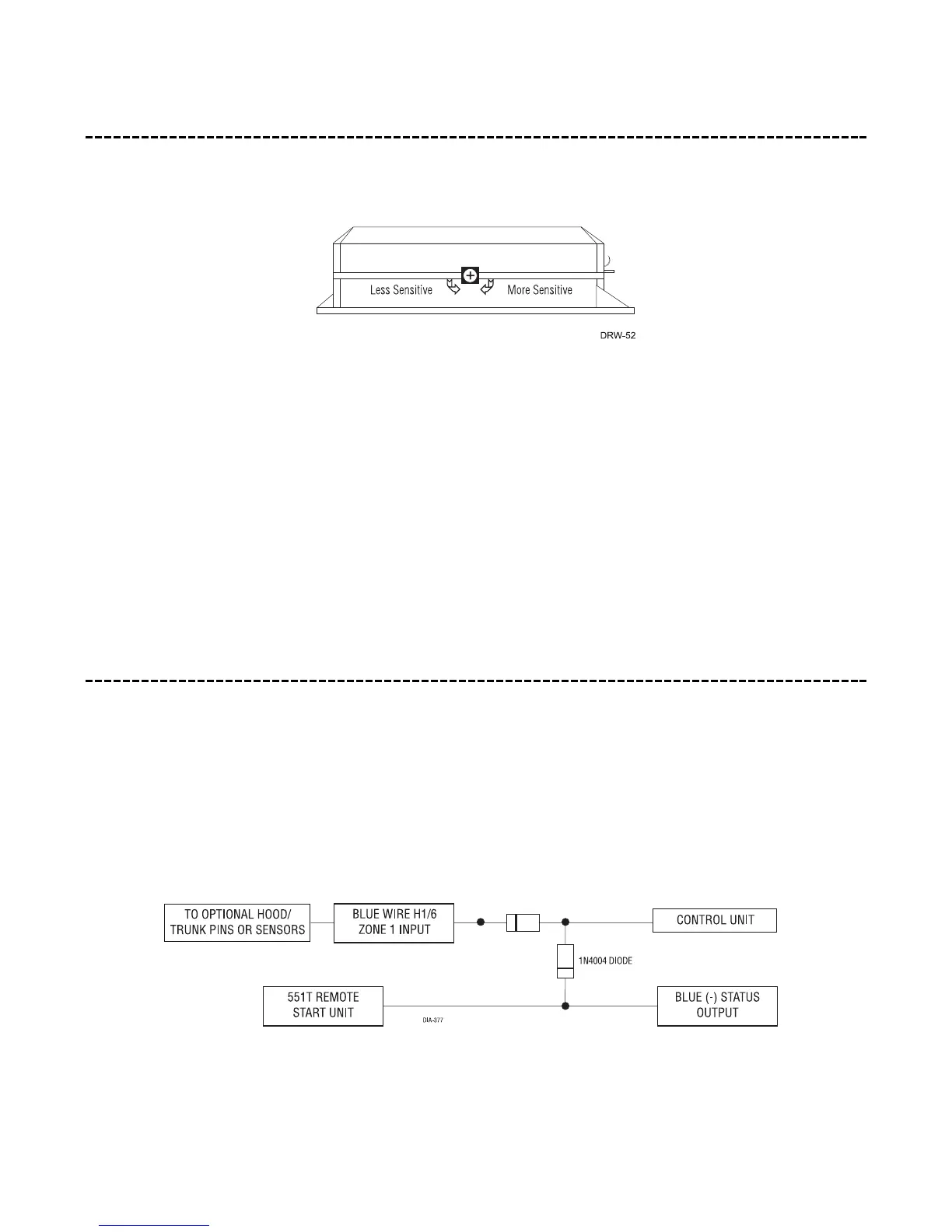
There is a Doubleguard
®
shock sensor inside the control unit. Adjustments are made via the rotary control as indi-
cated above. Since the shock sensor does not work well when mounted firmly to metal, we recommend against
screwing down the control module. The full trigger of the on-board shock sensor reports zone 2. (See Table of
Zones section of this guide.)
NOTE: When adjusting the sensor, it must be in the same mounting location that it will be after
the installation is completed. Adjusting the sensor and then relocating the module requires read-
justment.
bypassing sensor inputs
There are times when you need to temporarily bypass all sensor inputs to the unit, such as when remote start-
ing the vehicle. Anytime an auxiliary channel output is used, all inputs are bypassed for 5 seconds. During the
5 second bypass period, ground can be supplied to the H1/6 Blue wire without triggering the unit. When the 5
second bypass period ends, if the unit sees ground on the H1/6 Blue wire, all trigger inputs except the door
trigger input will remain bypassed until 5 seconds after ground is removed from the BLUE wire. This can be done
using the status output of a 551T remote start unit as shown below: