18 © 2001 Directed Electronics, Inc. Vista, CA
Before connecting this wire, remove the supplied fuse. Connect to the positive battery terminal or the constant
12V supply to the ignition switch.
NOTE: Always use a fuse within 12 inches of the point that you obtain (+)12V. Do not use the 15A
fuse in the harness for this purpose. This fuse protects the module itself.
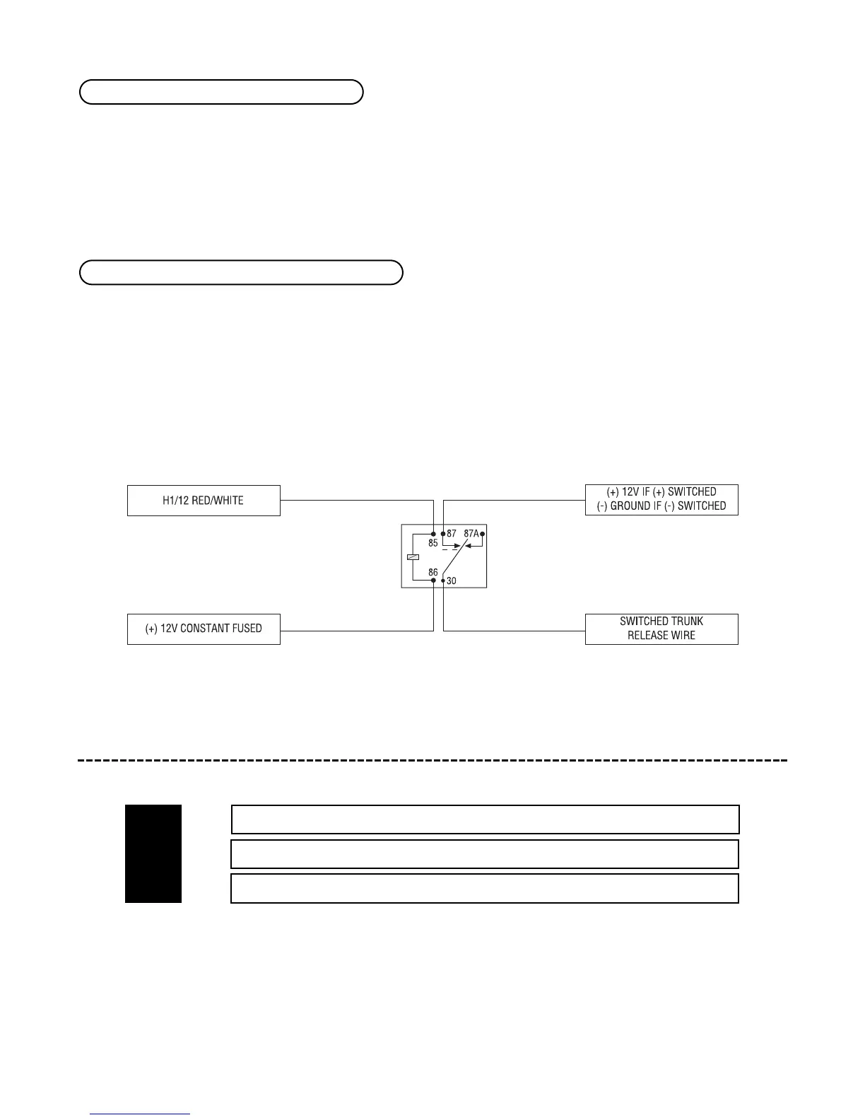
When the system receives the code controlling channel 2 for longer than 1.5 seconds, the red/white wire will
supply an output as long as the transmission continues. This output is often used to operate a trunk/hatch
release or other relay/driven function.
IMPORTANT! Never use this wire to drive anything except a relay or a low-current input! The
transistorized output can only supply 200 mA of current. Connecting directly to a
solenoid, motor, or other high-current device will cause it to fail.
door lock harness (H2), 3-pin connector
______
______
______
This system can control two common power door lock types without any additional parts! With certain vehicles,
or if an actuator is to be installed, either a 451M Door Lock Relay Satellite or two relays will be required.
IMPORTANT! If you mistake a Type C direct-wired system for a Type A positive-pulse system, the
module will be damaged!
BLUE (-) UNLOCK, (+) LOCK OUTPUT
EMPTY UNLESS USING 451M
GREEN (-) LOCK, (+) UNLOCK OUTPUT
H2/A
H2/B
H2/C
H1/12 RED/WHITE (-) 200 mA channel 2 output
H1/11 RED (+) 12V constant power input