© 2001 Directed Electronics, Inc. Vista, CA 17
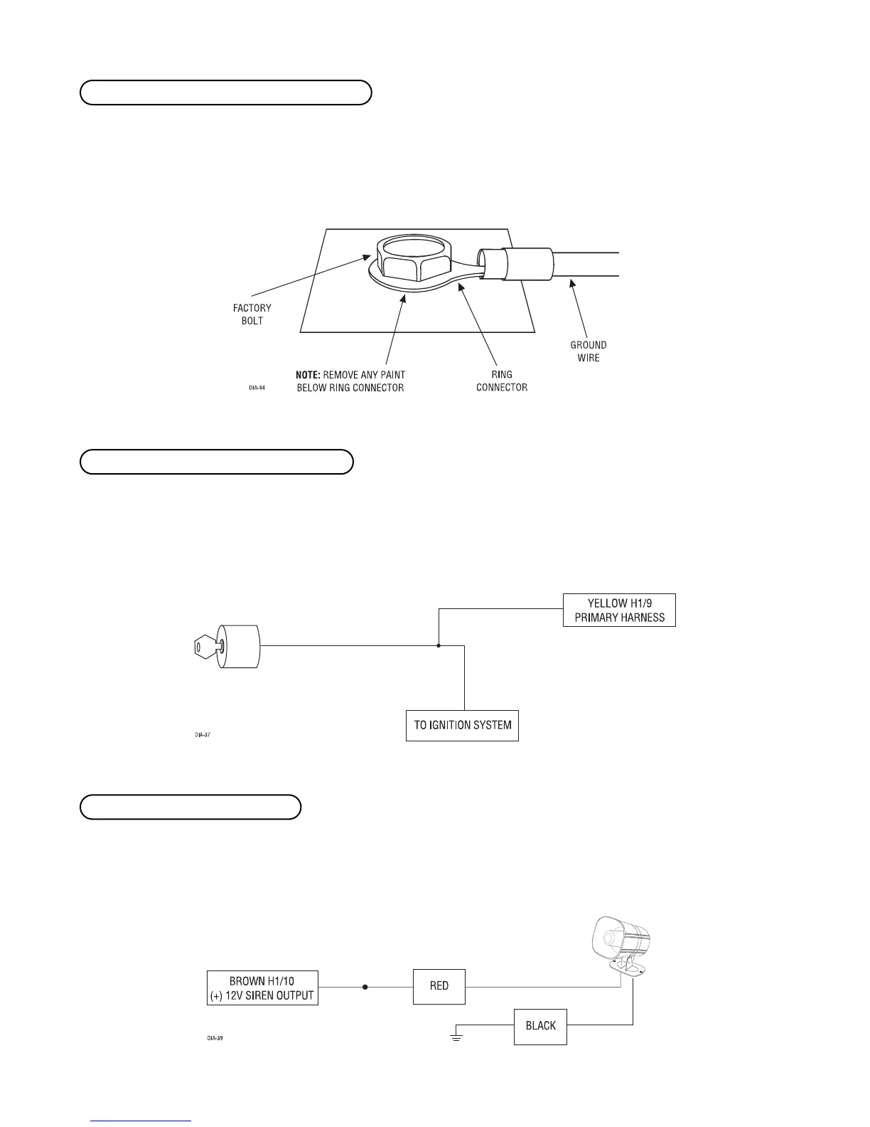
Remove any paint and connect this wire to bare metal, preferably with a factory bolt rather than your own screw.
(Screws tend to either strip or loosen with time.) We recommend grounding all your components, including the
siren, to the same point in the vehicle.
Connect this input to the (+)12V ignition wire. This wire must show (+)12V with the key in Run position and
during cranking. Take great care that this wire cannot be shorted to the chassis at any point. This wire will report
Zone 5.
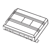
Connect this output to the red wire of the siren. Connect the black wire of the siren to (-) chassis ground, prefer-
ably at the same point you connect the control module’s black ground wire.
H1/10 BROWN (+) siren output
H1/9 YELLOW (+) ignition input, zone 5
H1/8 BLACK (-) chassis ground connection