© 2001 Directed Electronics, Inc. Vista, CA 13
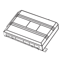
primary harness (H1), 12-pin connector
______
______
______
______
______
______
______
______
______
______
______
______
This guide describes in detail the connection of each wire. Also included are possible applications of each wire.
This system was designed with the ultimate in flexibility and security in mind. Many of the wires have more than
one possible function. Please read carefully to ensure a thorough understanding of this unit.
This wire supplies a (-) ground as long as the system is armed. This output ceases as soon as the system is dis-
armed. The orange wire is used to control the optional starter kill relay. It can supply up to 500 mA of current.
IMPORTANT! Never interrupt any wire other than the starter wire.
H1/1 ORANGE (-) ground-when-armed output
primary harness wire connection guide
RED/WHITE (-) 200 mA CHANNEL 2 VALIDITY OUTPUT
RED (+) CONSTANT POWER INPUT
BROWN (+) SIREN OUTPUT
YELLOW (+) SWITCHED IGNITION INPUT, ZONE 5
BLACK (-) CHASSIS GROUND INPUT
VIOLET (+) DOOR TRIGGER INPUT, ZONE 3
BLUE (-) INSTANT TRIGGER INPUT, ZONE 1
GREEN (-) DOOR TRIGGER INPUT, ZONE 3
BLACK/WHITE (-) 200 mA HORN HONK OUTPUT
WHITE/BLUE (-) 200 mA CHANNEL 3 SELECTABLE OUTPUT
WHITE (-) 200 mA LIGHT FLASH OUTPUT
ORANGE (-) 500 mA ARMED OUTPUT
H1/1
H1/2
H1/3
H1/4
H1/5
H1/6
H1/7
H1/8
H1/9
H1/10
H1/11
H1/12
primary harness wiring diagram