© 2001 Directed Electronics, Inc. Vista, CA 7
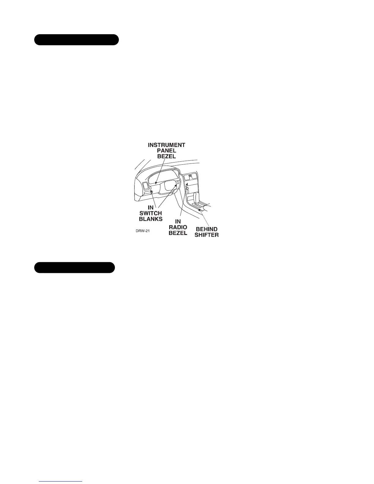
Things to remember when positioning the Status LED:
■ It should be visible from both sides and the rear of the vehicle, if possible.
■ It needs at least
1
/2-inch clearance to the rear.
■ It is easiest to use a small removable panel, such as a switch blank or a dash bezel. Remove it before drilling
your
9
/32-inch hole.
■ Use quick-disconnects near the LED wires if the panel is removable. This allows mechanics or other installers
to remove the panel without cutting the wires.
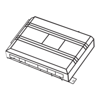
If the optional Failsafe
®
Starter Kill Relay or its connections are immediately visible upon removal of the under-
dash panel, they can easily be bypassed. Always make the relay and its connections difficult to discern from the
factory wiring! Exposed yellow butt connectors do not look like factory parts, and will not fool anyone! For this
reason, routing the starter kill wires away from the steering column is recommended.
optional starter kill relay
locations for the status LED