12
Shielding If shielded, Aluminum/Mylar shield (100% coverage) with TC
drain wire
UL temperature rating 32–167°F (0–75°C)
Voltage 300 Vac, power limited
Listing UL: NEC CL2P, or better
1 Remove power from the Room Controller.
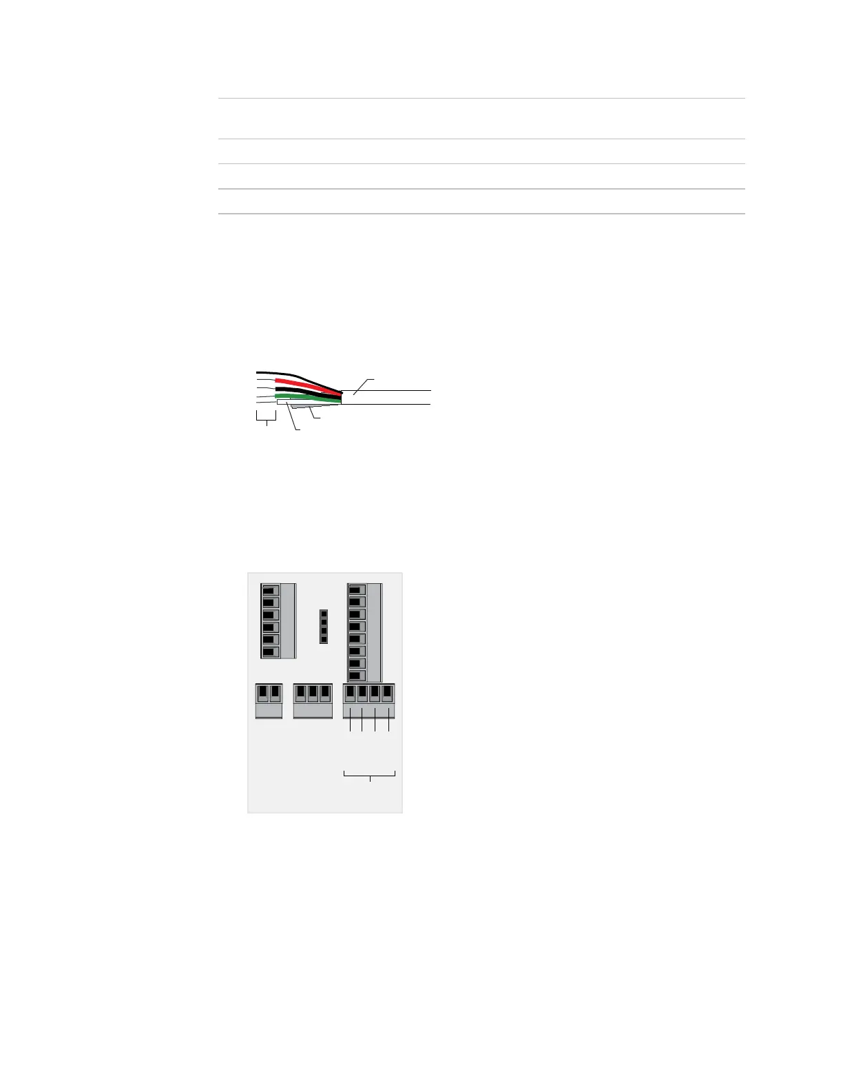
2 Partially cut, then bend and pull off the outer jacket of the Rnet cable(s). Do not nick
the inner insulation.
3
Inner insulation
Outer jacket
Foil shield
.25 in.
(.6 cm)
4 Strip about .25 inch (.6 cm) of the inner insulation from each wire.
5 Wire each terminal on the Room Controller's Rnet port to the terminal of the same
name on the RS room sensor.
NOTE If using shielded wire, connect the shield wire and the ground wire to the Gnd
terminal.
Wire to
Rnet
Rnet +
Ground
Rnet –
+12V
6 Apply power to the Room Controller.
To wire an RS
room sensor to
the Room
Controller
 Loading...