55
T
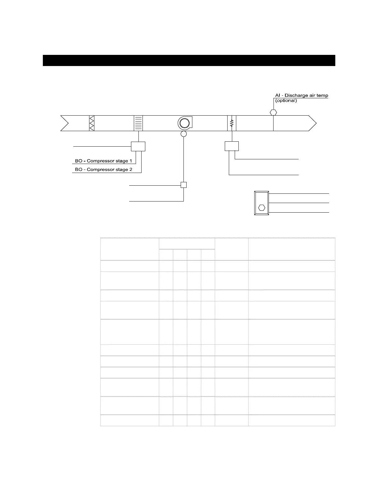
AI - Zone temp
AI - Zone setpoint adjust
BI - Zone override
RA
DA
BO - Fan start/stop
BI - Fan status
(optional)
M
HP
BO - Reversing valve
Elec
BO - Heating stage 2
(optional)
BO - Heating stage 1
(optional)
CT
T
Zone temp X Internal
Zone setpoint
adjust
X Internal
Zone override X Internal
Discharge air temp X UI-2 Optional – Requires sensor
(Type II thermistor)
Fan status X UI-4 Optional - Dry contact
Short input to ground if
not used.
Compressor stage 1 X DO-1 (Y1) Relay output
Compressor stage 2 X DO-2 (Y2) Relay output
Fan start/stop X DO-3 (G) Relay output
Supplemental heat
stage 1
X DO-4 (W1) Optional – Relay output
Supplemental heat
stage 2
X DO-5 (W2) Optional – Relay output
Reversing valve X DO-6 Relay output. Closed = Heating
#4: Air source heat pump - intermittent fan - reverse to heat
Control schematic
Point list
 Loading...