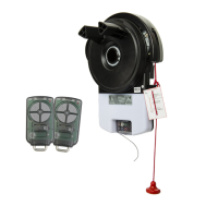
8
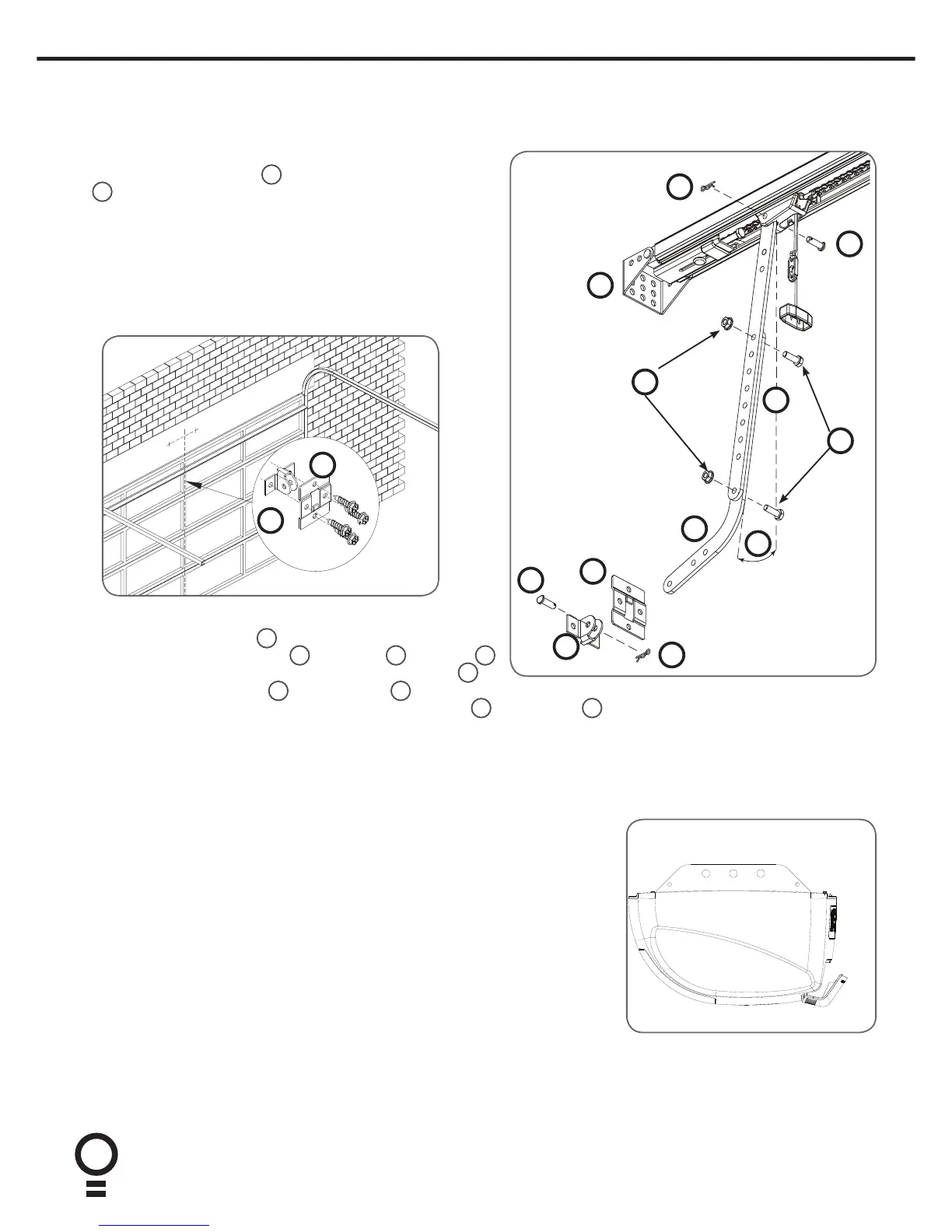
9. Mounting Brackets and Arms
Mounting The Door Bracket:
a. The door bracket locator
6
is placed over the door bracket
7
, on the door’s centre line one-third down the top panel and
mounted using M6 or equivalent screws (not supplied),
b. STEEL DOORS ONLY: Bracket can be welded in place.
NOTE: If in doubt about the door’s strength, reinforcement
may be added to the door’s frame where necessary. Door
damage may occur if the bracket is installed on a panel
with insufficient strength. The opener’s warranty does not
cover damage caused to the door and/or door panels.
Attaching the Arms
a. Assemble the bent arm
3
(connecting to the door) to the
right side of the straight arm
4
with bolts
9
and nuts
12
supplied in the accessory pack. Connect the straight arm
4
to
7
6
6
11
8
3
12
5
9
8
11
7
4
10. Connect to Power
Initial Preparation:
a. Swing open the controls cover to gain the access to the controls panel and
swing back into it position when setup is completed.
b. Engage the C-Rail’s trolley (attached to the door via the arms) with the
chain index by moving the door.
c. If the trolley does not “click” firmly onto the chain index, ensure that
the manual release cord is not in the disengaged position by pulling it
backwards.
NOTE: This cover has a label that says “Do not remove” however, this only
applies during normal operation. This cover must be removed to setup the
opener. Remove the button cover with a blade screwdriver.
d. Switch power on to the opener. The red CLOSE LIMIT LED will be flashing.
e. Press and hold the MINUS (-) button - the door should start closing. If door
starts to close, release button.
NOTE: If the door opens, release the MINUS (-) button and press the OPERATE
button once to change the motor’s direction.
the shuttle with a clevis pin
11
and a pin snap
8
. Always use both bent and straight arms.
b. Connect the assembled arm to the bracket with clevis pin
11
and pin snap
8
. The angle “A” must be more than 10°.
A