GS1 Series AC Drive User Manual
2–11
Chapter 2: Installation and Wiring
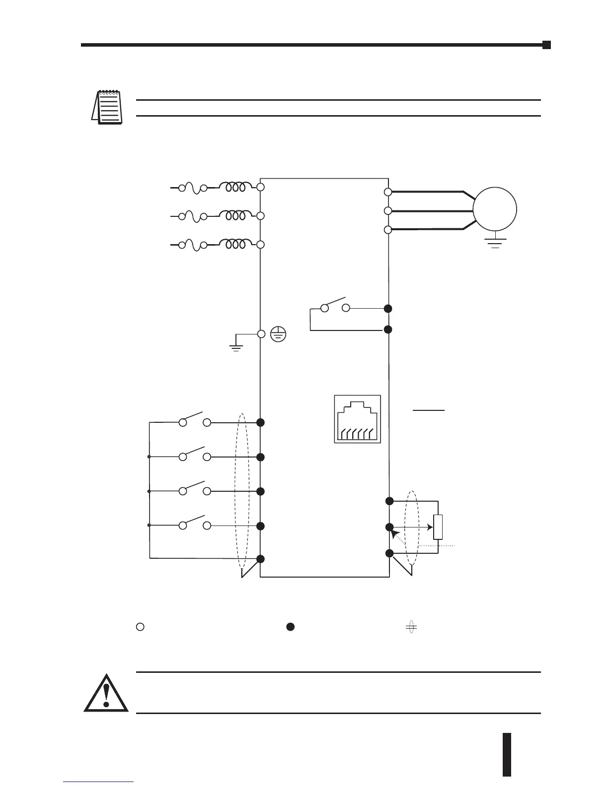
Basic Wiring Diagram
Note: Users must connect wiring according to the circuit diagram shown below.
WARNING: Do not plug a modem or telephone into the GS1 RJ-11 Serial Comm Port, or
permanent damage may result. Terminals 1 and 2 must not be used as a power source
for your communication connection.
Control circuit terminal Shielded leadsMain circuit (power) terminals
★Factory default: output frequency determined by the potentiometer on the keypad.
Power Source *
IM
200-240V±10%
(50/60Hz±5%)
GS1-xxxx
AC Motor
T3
T1
T2
Potentiometer
3K~5K⏲
+10V 10mA
(max)
AI
CM
Analog voltage
0-10VDC
Analog current
4-20mA
Grounding resistance
less than 0.1⏲
* Use terminals L1 and L2
for single phase models
L1
L3
L2
100-120V±10%
(50/60Hz ±5%)
R1O
R1
★Factory default:
AC Drive Running
Multi-function output contacts
120VAC/24VDC @5A
230VAC @2.5A
16
RJ-11 Serial Comm Port
Communication
Port
RJ-11
Pin-out
1: +17V
2: GND
3: SG-
4: SG+
★Factory default:
DI1
DI2
DI3
DI4
CM
Common Signal
Forward/Stop
Reverse/Stop
External Fault (N.0)
Multi-speed 1
 Loading...


