DirectLOGIC MODBUS Ladder Programming (cont.)
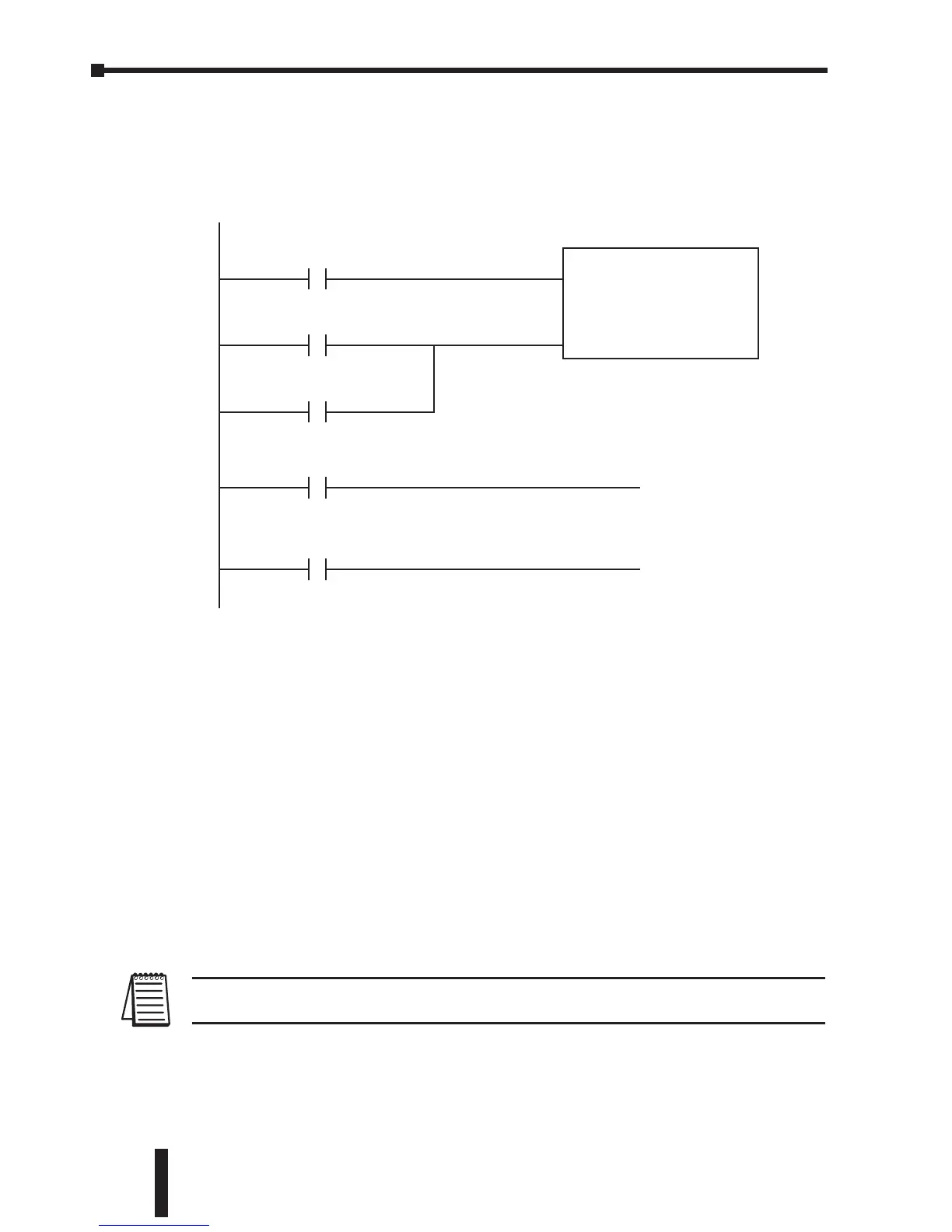
Rungs 2 through 4 monitor the number of times the PLC fails in communicating with
the AC drive. These instructions set the C50 bit (to be used for alarm or shut-down)
based on the number of times the SP117 bit is active in one minute. In this example
the C50 bit will be set if the number of errors exceed 20 in one minute.
Block Transfer
There is a group of block transfer parameters available in the GS1 AC drive (9.11 to
9.20). This contiguous block of parameters can be used to "group" miscellaneous
parameters throughout the drive. This will allow you to update these miscellaneous
parameters in one block instead of having to use multiple WX or RX commands.
For example: If you need to change the Slip Compensation (2-01), accel time (1-01),
decel time (1-02), and multi-speed 1 (5-01), this would typically take three different
WX commands because the parameters are non-contiguous. If you set 9-11 to 2-01,
9-12 to 1-01, 9-13 to 1-02, and 9-14 to 5-01, then all of these parameters could be
controlled using one WX command.
Rung 5 writes the values from V2000 to V2023 to the drive parameters 9-11 to
9-20. In the WX box, the value is V4413. 4413 is an octal number like all addresses
in the DirectLOGIC PLCs. If you convert 4413 octal to hex, you get 90B. 90B is the
address for parameter 9-11.
Note: Refer to your PLC User Manual for more specifics on MODBUS addressing and
address conversions.
Chapter 5: GS1 MODBUS Communications
GS1 Series AC Drive User Manual
5–10
 Loading...


