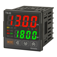
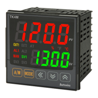
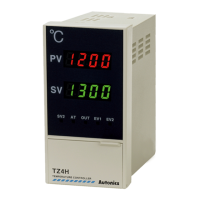
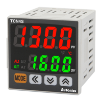
Table of Contents
X © Copyright Reserved Autonics Co., Ltd.
6.1.3 Input temperature sensor unit .................................................................... 42
6.1.4 Input correction ........................................................................................... 43
6.1.5 Input digital filter ......................................................................................... 43
6.1.6 SV high/low-limit value ............................................................................... 44
6.2 Control output .......................................................................................................... 45
6.2.1 Control output operation mode ................................................................... 45
6.2.2 Deadband/Overlap band ............................................................................ 47
6.2.3 MV high/low-limit value ............................................................................... 51
6.2.4 Ramp function ............................................................................................ 52
6.2.5 Auto/Manual control ................................................................................... 54
6.2.6 Manual control baseline MV ....................................................................... 54
6.2.7 Manual control initial MV ............................................................................ 55
6.2.8 Control output ............................................................................................. 55
6.3 Temperature control ................................................................................................ 56
6.3.1 Temperature control method ...................................................................... 56
6.3.2 ON/OFF control .......................................................................................... 56
6.3.3 PID control .................................................................................................. 57
6.3.4 Auto-tuning ................................................................................................. 60
6.4 Alarm output ............................................................................................................ 62
6.4.1 Alarm output target channel ....................................................................... 62
6.4.2 Alarm output operating mode ..................................................................... 63
6.4.3 Alarm output option .................................................................................... 64
6.4.4 Alarm SV .................................................................................................... 65
6.4.5 Alarm output hysteresis .............................................................................. 66
6.4.6 Alarm output method .................................................................................. 66
6.4.7 Alarm output delay ..................................................................................... 67
6.4.8 Loop break alarm(LBA) .............................................................................. 68
6.4.9 Sensor break alarm .................................................................................... 71
6.4.10 Heater burnout alarm ................................................................................. 71
6.4.11 Alarm output OFF ....................................................................................... 73
6.4.12 Alarm output examples ............................................................................... 74
6.5 Communications ...................................................................................................... 77
6.5.1 Communication address ............................................................................. 77
6.5.2 Communications speed settings ................................................................ 78
6.5.3 Communications parity bit .......................................................................... 78
6.5.4 Communication stop bit .............................................................................. 79
6.5.5 Response wait time .................................................................................... 79
6.5.6 Enable/Disable communications writing ..................................................... 79
6.5.7 USB
-to-Serial connection ........................................................................... 80
6.6 Monitoring function .................................................................................................. 81
6.6.1 Control output MV monitoring .................................................................... 81
6.6.2 Heating MV monitoring ............................................................................... 81
6.6.3 Cooling MV monitoring ............................................................................... 81
6.6.4 Heater current monitoring ........................................................................... 81
6.7 Run/Stop function .................................................................................................... 82
6.7.1 Control output for STOP ............................................................................. 82
6.7.2 Alarm output for STOP ............................................................................... 82
6.8 Multi SV ................................................................................................................... 83
 Loading...


