1 Product Introduction
© Copyright Reserved Autonics Co., Ltd. 21
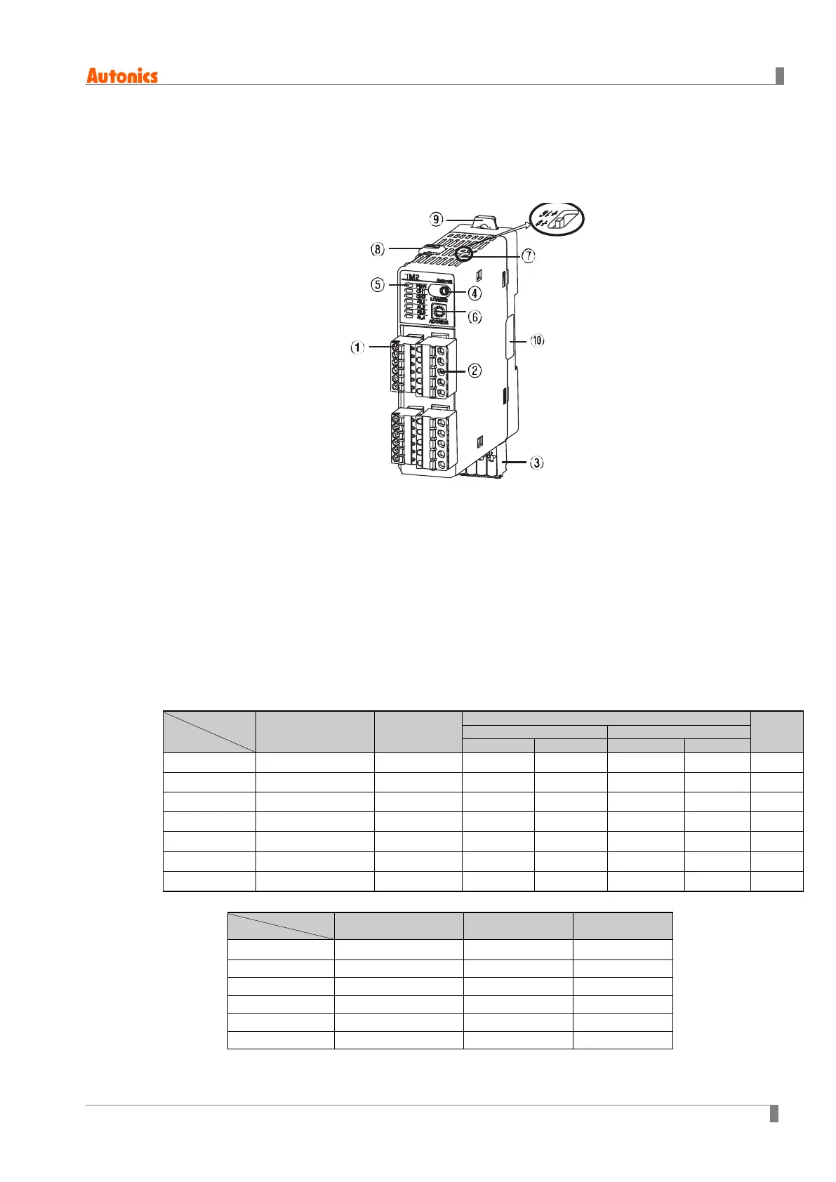
1.4 Parts and features
1.4.1 Front parts
① Sensor input connector
② Control output connector
③ Power/Comm. terminal [only for basic module (TM□-□2□B)]
Suppling power to basic/expansion modules and communicating with over 1 module (s).
④ PC loader port:
It is the PC loader port for serial communication between one module and PC to set
parameter and monitoring by DAQMaster. Use this for connecting SCM-US (USB to serial
converter, sold separately).
※When using PC loader port (connecting SCM-US), communication via power/comm.
terminal is blocked and monitoring is not available
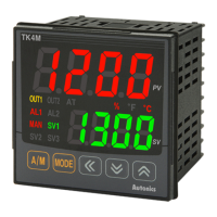
⑤ Indicators
TM2 Series
Initial power ON
※
1
Control
output
Auto-
tuning
※
2
※
3
ON ON - - - - ON
CH1 (red) Flashes (2,400bps) ON - - - - Flash
CH2 (red) Flashes (4,800bps) ON - - - - Flash
AL1 (yellow) Flashes (9,600bps)
ON
※
4
OFF ON OFF ON OFF
AL2 (yellow) Flashes (19,200bps)
ON
※
5
OFF ON OFF ON OFF
AL3 Flashes (38,400bps) - OFF ON OFF ON OFF
AL4 - - OFF ON OFF ON OFF
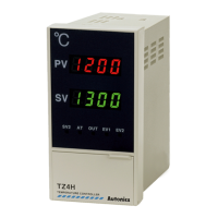
⑥ TM4 Series
Initial power ON
※
1
Control output
Auto-tuning
※2
PWR (green)
※
3
ON ON ON
CH1 (red) Flashes (2,400bps) ON Flash
CH3 (red) Flashes (9,600bps) ON Flash
CH4 (red) Flashes (19,200bps) ON Flash
Flashes (38,400bps)
 Loading...