9
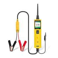
While the tool is in DC Voltage mode, contact the probe tip to
a POSITIVE circuit. The red LED will light and the LCD
displays the voltage with a resolution of 0.1V. If the beep is
turned on, a high pitched tone will sound.
If contact the probe tip to a NEGATIVE circuit, the green LED
will light and the LCD displays the voltage with a resolution of
0.1V. If the beep is turned on, a low pitched tone will sound.
If contact the probe tip to an OPEN circuit, neither of the LED
will light.
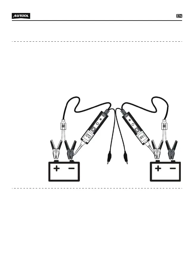
While the tool is in Resistance mode, using the probe tip with
chassis ground or the auxiliary ground lead, continuity can be
tested on wires and components attached or disconnected
from the vehicle’s electrical system.
When the probe tip is contacting a good ground, the LCD will
indicate “0.0Ω ” and green LED will be on. If the tone feature
is turned on, a low pitched tone will sound.
TEST APPLICATIONS
Voltage &
Polarity
testing
Continuity
testing
●
●
●
●
●