11
Once you extract a DTC from the vehicle and realize that trouble-
shooting begins with some kind of sensor circuit, there is a quick
test you can perform to verify the code.
Testing your sensor is easy while using the tool. For example, you
suspect there is a problem with your M.A.P. Sensor circuit, then
follow the procedure involved with testing this sensor:
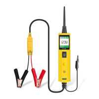
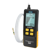
While the tool is in DC Voltage mode, by using the probe tip in
connection with the auxiliary ground lead, components can be
activated right in your hand, thereby testing their functions.
Connect the auxiliary ground lead to the negative terminal or
ground side of the component being tested. Then contact the
probe tip to the positive terminal of the component, the green
LED should light, indicating continuity through the component.
While keeping an eye on the green LED, quickly press and
release the power switch forward. If the green LED went out and
the red LED came on, you may proceed with further activation.
Rock the power switch forward and hold it down to provide power
Signal
circuit
testing
Activating
compo-
nents in
your hand
●
●
●
●
●
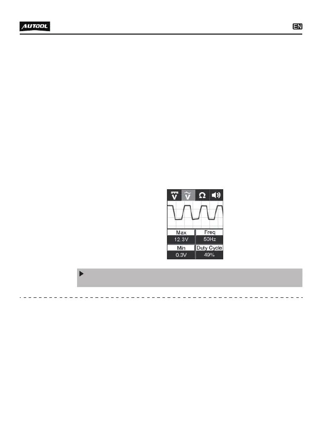
Set the tool in AC Voltage mode, using the probe tip with
chassis ground or the auxiliary ground lead.
Connect vacuum pump to MAP sensor.
Contact the probe tip to the MAP sensor positive terminal and
observe the LCD readings which should be a sine wave in
normal condition.
Apply vacuum.
Release vacuum and observe the LCD readings.
If the LCD readings are abnormal, there is a problem with this
sensor.
to your component. With the power switch rocked forward, power
will flow from the positive lead on the battery into the probe tip,
through the tip into the component’s positive terminal, into the
component and out of the component, through the auxiliary
ground lead and back into the tool, and back to the vehicle
battery’s ground.