LED indicators
Operators Handbook, Fire Alarm Control panel BX-10, P-BX10/FE - Rev.F, 030123, Autronica Fire and Security AS
Page 9
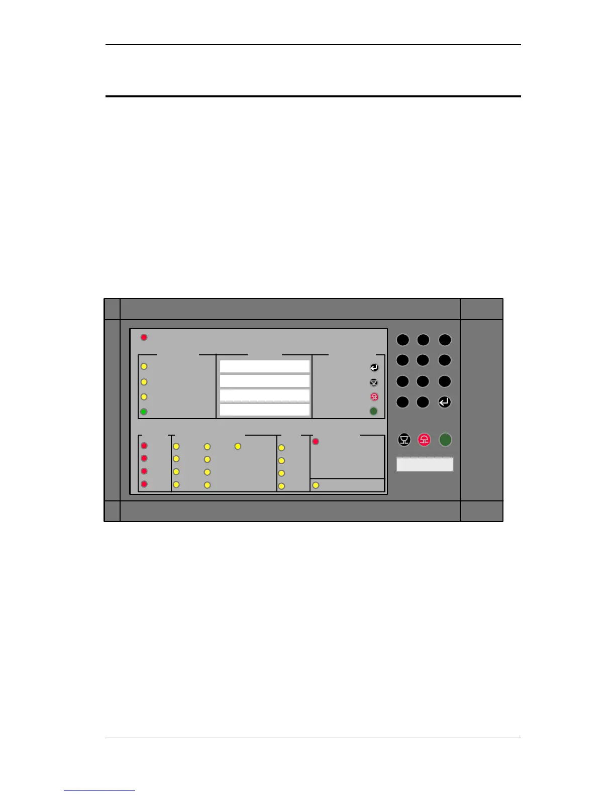
3. LED indicators
3.1 Summary
The panel front comprises 24 LED indicators. The individual
characteristics and response modes for these are given in subsequent
chapters concerning the various events/functions.
In addition, a detailed description of the indicator functions is provided
in the Appendix at the back of this manual.
The instant an alarm signal is activated, the LED indicators for FIRE and
FAULT will flash in time with the intermittent internal audio warning.
s
ALARM
Test
Fault
Disabled
Power
Zone 1
Zone 2
Zone 3
Zone 4
 Loading...