Testing indicator lights and internal buzzer
Operators Handbook, Fire Alarm Control panel BX-10, P-BX10/FE - Rev.F, 030123, Autronica Fire and Security AS
Page 22
s
ALARM
Test
Fault
Disabled
Power
Zone 1
Zone 2
Zone 3
Zone 4
Alarms
Contr.
Al -outp.
Fault/Disabled/Test
Battery
Power
Earth
Fault
Zone 1
Zone 2
Zone 3
Zone 4
Fault outp.
.
Operator
Imm. alarm
InformationAlarm
System Zone
Operator
1:
2:
3:
4:
Access code: xxx
Silence int. buzzer
Silence/res. alarms
Reset
Autronica Fire & Security
System
0
C
987
6
5
4
3
21
BX-10
R
R
Alarm call activated
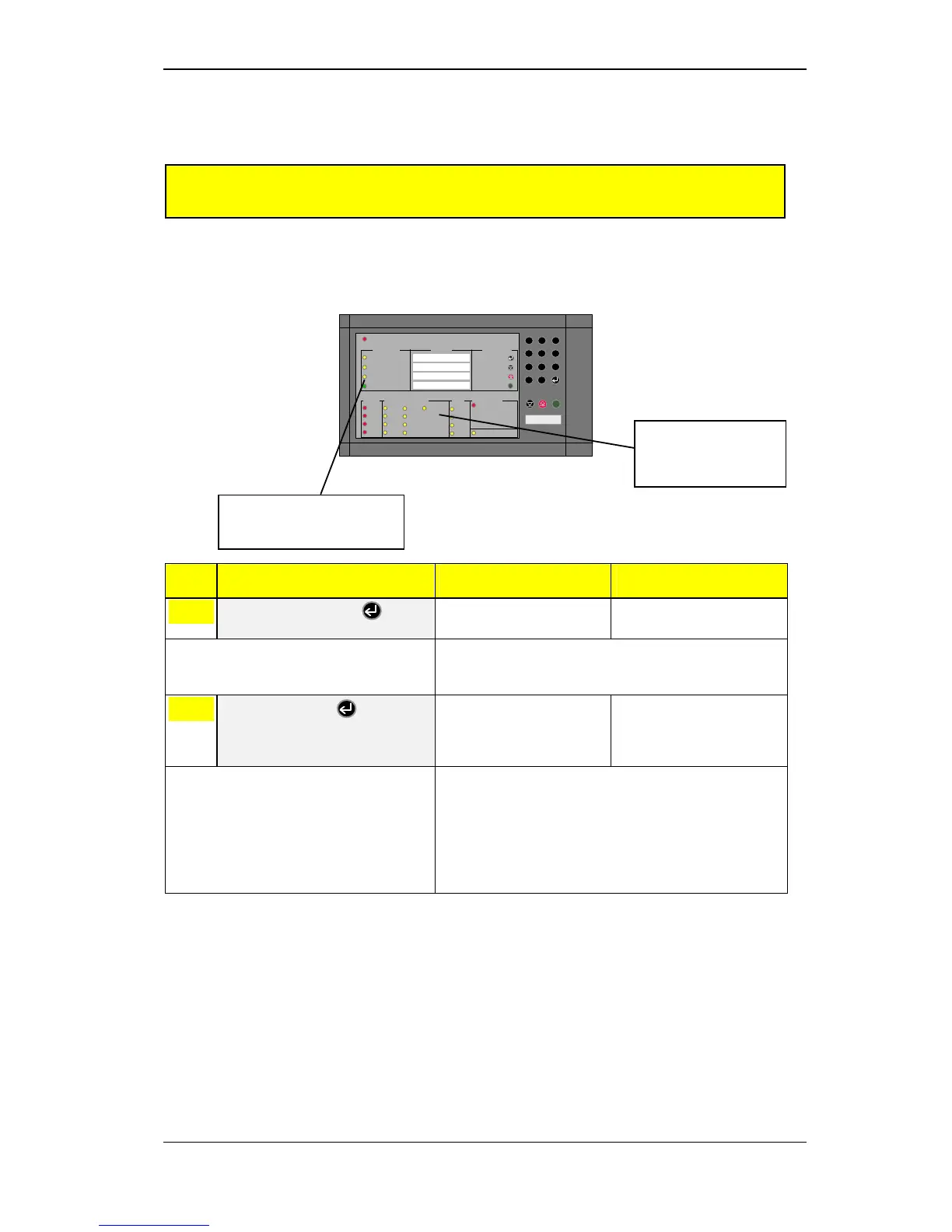
8.2 Activating from the front panel
IMPORTANT: If the alarm delay is activated from an external switch, it
is not possible to deactivate the delay from the control panel.
Step Necessary Action Visual Warning Status Audio Warning Status
1
Key operator code +
The yellow operator level
indicator will come on.
Note: The default alarm delay function (day/night function) is key-
code 9, and includes the AK1, AK2 and BMA outputs. The
default time delay is 5 minutes.
2
Enter key code +
The yellow DISABLING and
IMMEDIATE WARNING
DISABLED indicators will
come on.
Note : The 5-minute alarm delay on the alarm outputs(AK1 and AK2)
and general alarm output (BMA) will be activated.
The yellow DISABLING and IMMEDIATE WARNING
DISABLED indicators will remain on until the function is
deactivated by repeating the procedure, or by it being
automatically restored to normal (after 12 hours) by the time-
programmed safety restore function.
*Maritime version; see appendix 10.2.
The yellow IMMEDIATE
WARNING DISABLED
indicator will come on.
* Not for BX-10M
Disabling/restoring of the immediate warning (or alarm delay) function can be implemented from
the front panel using an operator code when it is necessary to activate/deactivate the alarm delay
at special times.
The yellow DISABLING
indicator will come on.
* Not for BX-10M
 Loading...