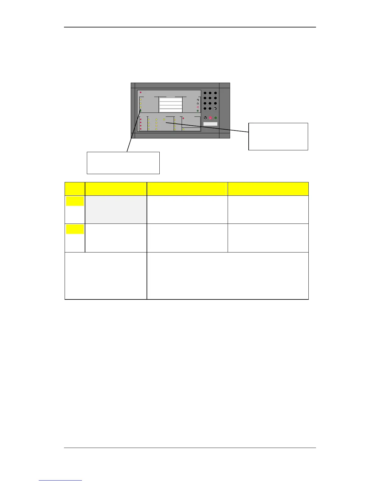
Testing indicator lights and internal buzzer
Operators Handbook, Fire Alarm Control panel BX-10, P-BX10/FE - Rev.F, 030123, Autronica Fire and Security AS
Page 23
s
ALARM
Test
Fault
Disabled
Power
Zone 1
Zone 2
Zone 3
Zone 4
Alarms
Contr.
Al -outp.
Fault/Disabled/Test
Battery
Power
Earth
Fault
Zone 1
Zone 2
Zone 3
Zone 4
Fault outp.
.
Operator
Imm. alarm
InformationAlarm
System Zone
Operator
1:
2:
3:
4:
Access code: xxx
Silence int. buzzer
Silence/res. alarms
Reset
Autronica Fire & Security
System
0
C
987
6
5
4
3
21
BX-10
R
R
Alarm call activated
Activating from an auxiliary switch
An auxiliary switch for activating/deactivating the alarm delay function
can be connected to terminals 60 and 64 in the control panel. The alarm
delay is activated when the switch is closed.
Step Necessary Action Visual Warning Status Audio Warning Status
1
Disable immediate
warning by closing the
auxiliary switch.
The yellow DISABLING and
IMMEDIATE WARNING
DISABLED indicators will come
on.
2
Restore immediate
warning function by
resetting auxiliary
switch.
Yellow DISABLING indicator and
IMMEDIATE WARNING
DISABLED indicator go out.
Note: The alarm delay on the alarm outputs and general common alarm output
(pre-programmed to 5 minutes) will be activated.
Function is automatically restored by the control panel after 12-hour time
lapse even though auxiliary disabling switch is active.
New delay period is activated by cancelling and re-activating the auxiliary
disabling switch.
*Maritime version; see appendix 10.2.
The yellow IMMEDIATE
WARNING DISABLED
indicator will come on.
* Not for BX-10M
The yellow DISABLING
indicator will come on.
* Not for BX-10M
 Loading...