Appendix
Operators Handbook, Fire Alarm Control panel BX-10, P-BX10/FE - Rev.F, 030123, Autronica Fire and Security AS
Page 27
10. Appendix
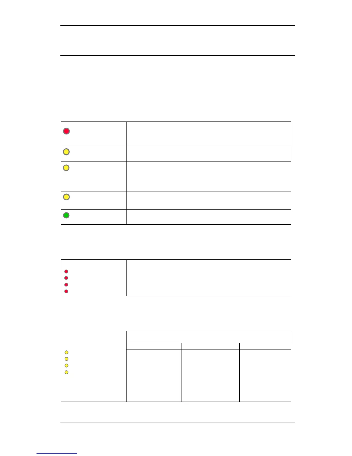
10.1 Summary of indicators
10.1.1 Main indicators
FIRE
Red indicator activated when the panel receives an alarm signal from a zone.
• Flashing red light on alarm.
• Constant red light when SILENCE ALARM is activated.
• Flashing red light with a new alarm (0.5 sec. ON, 0.5 sec. OFF).
Test
Yellow indicator activated during the testing of control panel functions.
• Constant yellow light during testing. (Test function not implemented).
Fault
Yellow error indicator activated by errors/faults in the system.
• Flashing yellow light denotes error/fault and will remain until the control
panel is reset (0.5 sec. ON, 1.5 sec. OFF).
• If a fault remains after resetting the panel, the error indicator will be activated
again.
Disabling
Yellow indicator comes on when a function is disabled.
• Remains lit as long as the function is disabled.
• Constant light when the panel is in delayed alarm mode (D/N function). *
On
Green indicator which comes on when a 230 V AC operating voltage or 24V
batteries are connected up to the control panel.
10.1.2 Alarm – detector zones
Alarm
zone 1
zone 2
zone 3
zone 4
Red indicator comes on when the control panel receives an alarm signal from the
respective detector zone.
• Flashing red light on alarm (0.5 sec. ON, 0.5 sec. OFF).
• Constant red light with operation of the SILENCE ALARM button.
• Flashing red light with new alarm.
• Light goes out when the control panel is reset.
10.1.3 Fault/disabling/testing - zones 1 - 4
Fault/Disabling/Test
Yellow indicators with 3 functions: fault in zone, disabling of zone, and testing of
zone (characteristics as per common indicator in sub-section 10.1.1).
Fault status
Disabling status
Test mode
Zone 1
Zone 2
Zone 3
Zone 4
Activated by break, short
circuit or high surge in
the loop.
• Flashing yellow light
with fault- remains
active until control
panel is reset.
• Goes out when
control panel is reset.
Disabling indication has
priority over fault or test.
• Constant yellow light
as long as the zone is
disabled.
•
Not implemented
* Not for maritime version BX-10M
 Loading...