Adjusting the drive control cable
25
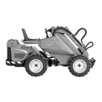
500 Series
DO NOT SPILL FUEL WHEN
REFUELING. SHOULD THIS
HAPPEN, WIPE THE FUEL AWAY
IMMEDIATELY IN ORDER TO
AVOID RISK OF FIRE.
ALWAYS STOP THE ENGINE
BEFORE REFUELING.
KEEP THE ENGINE AWAY FROM
OPEN FIRE.
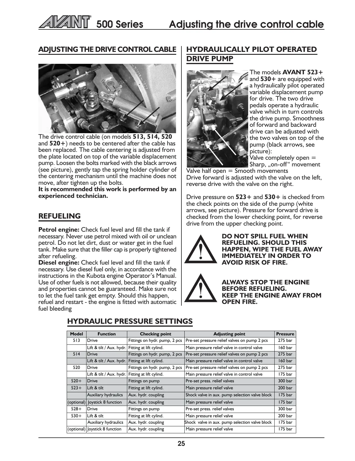
ADJUSTING THE DRIVE CONTROL CABLE
The drive control cable (on models 513, 514, 520
and 520+) needs to be centered after the cable has
been replaced. The cable centering is adjusted from
the plate located on top of the variable displacement
pump. Loosen the bolts marked with the black arrows
(see picture), gently tap the spring holder cylinder of
the centering mechanism until the machine does not
move, after tighten up the bolts.
It is recommended this work is performed by an
experienced technician.
REFUELING
Petrol engine: Check fuel level and fill the tank if
necessary. Never use petrol mixed with oil or unclean
petrol. Do not let dirt, dust or water get in the fuel
tank. Make sure that the filler cap is properly tightened
after refueling.
Diesel engine: Check fuel level and fill the tank if
necessary. Use diesel fuel only, in accordance with the
instructions in the Kubota engine Operators Manual.
Use of other fuels is not allowed, because their quality
and properties cannot be guaranteed. Make sure not
to let the fuel tank get empty. Should this happen,
refuel and restart - the engine is fitted with automatic
fuel bleeding
HYDRAULICALLY PILOT OPERATED
DRIVE PUMP
The models AVANT 523+
and 530+ are equipped with
a hydraulically pilot operated
variable displacement pump
for drive. The two drive
pedals operate a hydraulic
valve which in turn controls
the drive pump. Smoothness
of forward and backward
drive can be adjusted with
the two valves on top of the
pump (black arrows, see
picture):
Valve completely open =
Sharp, on-off movement
Valve half open = Smooth movements
Drive forward is adjusted with the valve on the left,
reverse drive with the valve on the right.
Drive pressure on 523+ and 530+ is checked from
the check points on the side of the pump (white
arrows, see picture). Pressure for forward drive is
checked from the lower checking point, for reverse
drive from the upper checking point.
HYDRAULIC PRESSURE SETTINGS
Model Function Checking point Adjusting point Pressure
513 Drive Fittings on hydr. pump, 2 pcs Pre-set pressure relief valves on pump 2 pcs 275 bar
Lift & tilt / Aux. hydr. Fitting at lift cylind. Main pressure relief valve in control valve 160 bar
514 Drive Fittings on hydr. pump, 2 pcs Pre-set pressure relief valves on pump 2 pcs 275 bar
Lift & tilt / Aux. hydr. Fitting at lift cylind. Main pressure relief valve in control valve 160 bar
520 Drive Fittings on hydr. pump, 2 pcs Pre-set pressure relief valves on pump 2 pcs 275 bar
Lift & tilt / Aux. hydr. Fitting at lift cylind. Main pressure relief valve in control valve 175 bar
520+ Drive Fittings on pump Pre-set press. relief valves 300 bar
523+ Lift & tilt Fitting at lift cylind. Main pressure relief valve 200 bar
Auxiliary hydraulics Aux. hydr. coupling Shock valve in aux. pump selection valve block 175 bar
(optional) Joystick 8 function Aux. hydr. coupling Main pressure relief valve 175 bar
528+ Drive Fittings on pump Pre-set press. relief valves 300 bar
530+ Lift & tilt Fitting at lift cylind. Main pressure relief valve 200 bar
Auxiliary hydraulics Aux. hydr. coupling Shock valve in aux. pump selection valve block 175 bar
(optional) Joystick 8 function Aux. hydr. coupling Main pressure relief valve 175 bar