Controls
12
500 Series
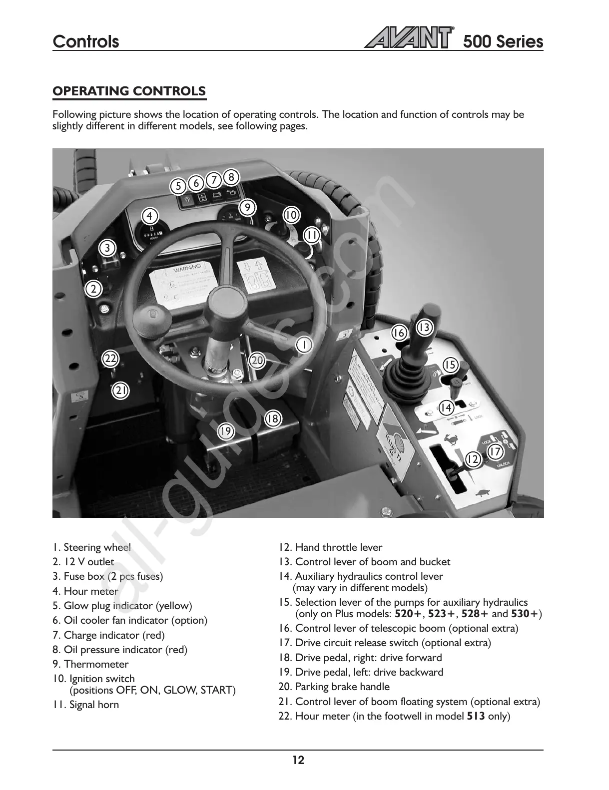
OPERATING CONTROLS
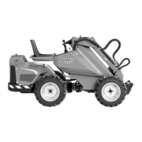
Following picture shows the location of operating controls. The location and function of controls may be
slightly different in different models, see following pages.
1. Steering wheel
2. 12 V outlet
3. Fuse box (2 pcs fuses)
4. Hour meter
5. Glow plug indicator (yellow)
6. Oil cooler fan indicator (option)
7. Charge indicator (red)
8. Oil pressure indicator (red)
9. Thermometer
10. Ignition switch
(positions OFF, ON, GLOW, START)
11. Signal horn
12. Hand throttle lever
13. Control lever of boom and bucket
14. Auxiliary hydraulics control lever
(may vary in different models)
15. Selection lever of the pumps for auxiliary hydraulics
(only on Plus models: 520+, 523+, 528+ and 530+)
16. Control lever of telescopic boom (optional extra)
17. Drive circuit release switch (optional extra)
18. Drive pedal, right: drive forward
19. Drive pedal, left: drive backward
20. Parking brake handle
21. Control lever of boom floating system (optional extra)
22. Hour meter (in the footwell in model 513 only)
1
12
2
3
4
5
6
7
8
9
10
11
13
14
15
16
17
18
19
20
21
22