Before you begin this procedure, ensure that the equipment rack meets these requirements:
• A space equivalent to the rack height of the switch is provided for each switch in an EIA
or IEC standard 19-inch (48.2 centimeter) or TIA 23-inch (58.4 centimeter) equipment
rack.
• The rack is bolted to the floor and braced if necessary.
• The rack is grounded to the same grounding electrode used by the power service in the
area. The ground path must be permanent and must not exceed 1 ohm of resistance from
the rack to the grounding electrode.
Caution:
When you mount the switch in a rack, do not stack units directly on top of one another in the
rack. Each unit must be secured to the rack with the appropriate mounting brackets.
Mounting brackets are not designed to support multiple units.
Single and multiple switch arrangements
This module describes standalone and stacked arrangements.
Navigation
• Standalone arrangement on page 18
•
Stack arrangement on page 18
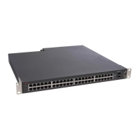
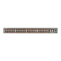
You can stack any of the 5000 Series switches. You can connect up to eight 5600 Series
devices in a stack to provide uninterrupted connectivity for up to 384 ports. Bandwidth in a
5600 Series stack is 144 Gbps.
Standalone arrangement
This module describes a standalone configuration.
Any one switch can operate in a standalone configuration. You can add more switches as your
traffic increases.
Stack arrangement
This module describes a stack arrangement.
You connect the switches in the stack by the stack connectors. You designate one unit as the
base unit by setting a switch on the back panel.
Installation fundamentals
18 Installing Avaya Ethernet Routing Switch 5000 Series December 2013
Comments? infodev@avaya.com

 Loading...


