Figure 26: Creating your own long VISCA cross cable
Procedure
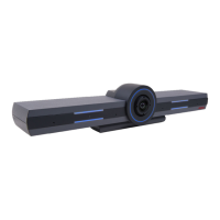
1. Remove the camera stabilizing cartons, to avoid damage to the system.
Caution:
Do not place the camera on top of the XT Codec Unit. It can cause the system to
overheat.
2. Verify the SYSTEM SELECT switch on the back panel of the new camera is set to 7.
This is only for Premium, Advanced, and Standard II cameras.
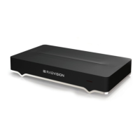
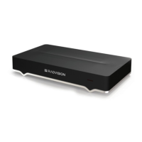
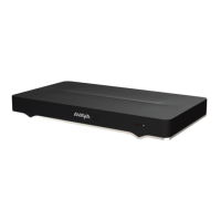
3. Connect the DVI port on the camera to the DVI connector on the XT Codec Unit (Figure 25:
Connecting an additional camera directly to the XT Series on page 53). The system
manages it as PC content.
—Or—
For the XT7000 Series, we recommend connecting the additional camera to the HDMI 2 port
on the XT Codec Unit (located under ). This keeps the DVI port available for a computer
connection.
4. Connect the power supply cable to the DC IN connector on the camera.
5. Plug the power supply cable into a power outlet.
6. (Optional for XT7000 Series and XT5000 Series only) To control the extra camera using the
same XT Remote Control Unit, connect one end of the crossed VISCA control cable to the
additional camera's IN (RS-232C) connector. Then connect the other end to the main
camera's OUT (RS-232C) connector (
Figure 25: Connecting an additional camera directly to
the XT Series on page 53).
7. Apply power to the camera.
Related links
Connecting Cameras or DVD players on page 49
Setting Up the XT Series Hardware
January 2017 Avaya Scopia
®
XT Series Deployment Guide 54
Comments on this document? infodev@avaya.com
 Loading...
