Note:
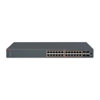
Indicator states are applicable to all models of VSP 4000 switches.
The following list describes the three port LEDs:
• Activity indicates the level of activity on the link.
• Link indicates the presence of an Ethernet link.
• Speed indicates the port speed (for example, 10 Mb/s, 100 Mb/s, 1000 Mb/s).
Table 16: RJ-45 Port LED state indicators
Label Color and Status Description
Speed/PoE+ Green, Blink The port is set to operate at 1000 Mbps with PoE.
Green, Steady The port is set to operate at 1000 Mbps without PoE
+.
Amber, Blink The port is set to operate at 100 Mbps with PoE+.
Amber, Steady The port is set to operate at 100 Mbps without PoE
+.
Amber, Green Pulse The port is experiencing a PoE+ error.
Off When the Link/Activity LED is green and the Speed
LED is off, the port is set to operate at 10 Mbps for
all models.
Link / Activity Green, Steady The link established but no data activity exists.
Green, Blink The link is established and data activity exists (the
blink rate indicates the level of activity).
Green, Slow Blink The port is administratively disabled.
Off Local/remote fault.
Table 17: SFP/SFP+ transceiver Port LED state indicators
Label Color and Status Description
In Use Green, Blink Not applicable.
Green, Steady The SFP port and the transmit port are active.
Amber, Blink Not applicable.
Amber, Steady SFP Installed—TX Port Inactive
Off No SFP transceiver is present.
Link / Activity Green, Blink Activity exists on the port.
Green, Slow Blink Software disabled this port.
Green, Steady The link is operating normally.
Off No link exists.
Check Light Emitting Diode (LED) on the Avaya Virtual Services Platform 4000
May 2016 Installing Avaya Virtual Services Platform 4850GTS Series 39
Comments on this document? infodev@avaya.com
 Loading...