XR Series Installation and Technical Instructions 23
20 mA Current Loop Wiring
1. Set the Communication Input Jumper (JP 1) to LOOP.
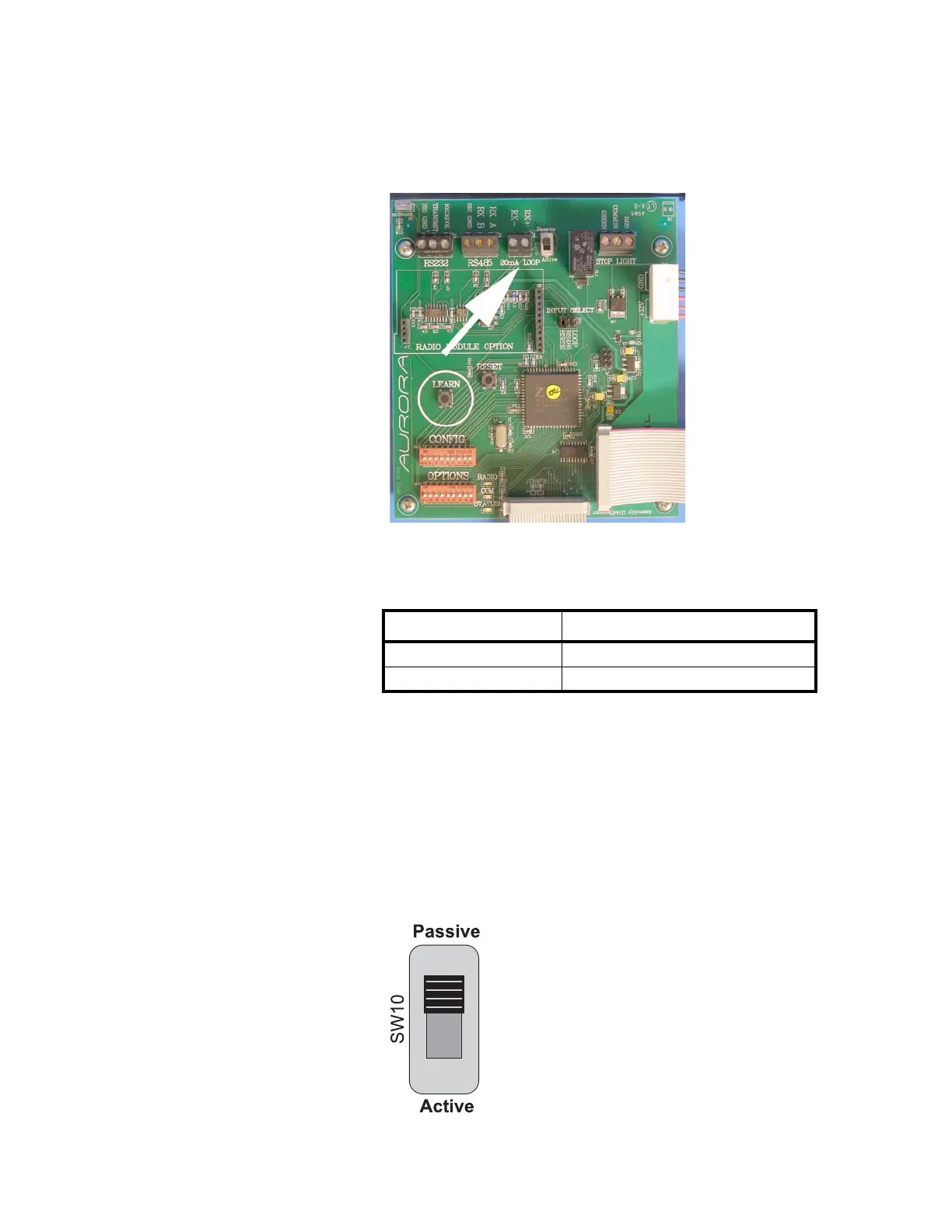
2. Terminate the indicator’s communication wires at the 20 mA Current
Loop terminal (J5), shown in Figure 3.5.
Figure 3.5 20mA Current Loop Terminal
See table below for pin assignments:
20 mA Current Loop Mode Switch
• After the current loop is wired, ACTIVE or PASSIVE mode must be
selected (SW 10) on the controller board.
• Select Active mode if the XR is required to supply the current to the
communicating device.
• Select Passive mode if the communicating device (indicator) supplies
the current to the XR.
• If unsure of these requirements, check the device’s manual.
Figure 3.6 20 mA Mode Switch
INDICATOR TO XR
20 mA TX + RECEIVE POSITIVE (RX +)
20 mA TX - RECEIVE NEGATIVE (RX -)
 Loading...