30 XR Series Installation and Technical Instructions
Wireless Communication
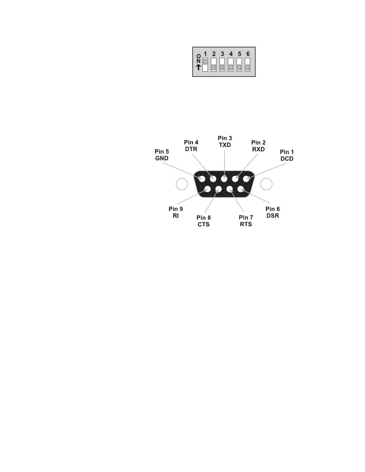
Figure 4.5 shows the RS-232 DIP switch settings.
Figure 4.5 DIP switch settings
DIP switch settings are read and applied only while powering on.
Figure 4.6 shows the RS-232 DB-9 serial connector and the pin
assignments.
Figure 4.6 RS-232 DB-9 serial connector pin assignments
1. The base station’s default communication settings are:
Baud Rate 9600 Data Bits 8
Parity None Stop Bits 1
If necessary, adjust the base station’s communication settings to
match the indicator (or other communicating device). This requires a
computer and XStream software package. Refer to the XStream Start-
Up Guide for information.
2. Power the base station using the supplied 12VDC power supply.
3. Power up the indicator and base station to transmit radio signals.
 Loading...