Pro Tools | HD I/O Guide6
Loop Master LED
The LOOP MASTER LED indicates which audio
interface is the master peripheral. The Loop Mas-
ter LED will be continuously lit on the current
Loop Master peripheral only, and unlit on all other
peripherals. (Only one Avid HD peripheral can be
Loop Master at a time.) The Loop Master LED will
always be lit with a single interface.
With HDX hardware, Loop Master defaults to the
first audio interface connected to DigiLink Mini
Port 1 on the first card in the system.
With HD Native hardware, Loop Master defaults
to the first audio interface connected to DigiLink
Mini Port 1 on the HD Native card.
For Pro Tools|HD systems, Loop Master defaults
to the first audio interface connected to the pri-
mary, or “core” Pro Tools|HD card. On
Pro Tools|HD (for PCIe), this is the Accel Core
card. On Pro Tools|HD (for PCI), this is the HD
Core card.
Sync Mode LEDs
The SYNC MODE LEDs indicate the current
Clock Source as set in Pro Tools.
INT (Internal)
Indicates the HD I/O sample clock is
generated by its internal clock, as determined by
the session Sample Rate.
DIG (Digital)
Indicates that an external AES/EBU,
TDIF, Optical (ADAT), Optical (ADAT S/MUX),
or S/PDIF device is providing system clock. If no
valid clock source is detected, HD I/O will switch
to internal clock, the DIG LED will flash, and an
error message will appear on-screen in Pro Tools.
LOOP
Indicates that the HD I/O is slaving to an-
other Avid HD audio interface or SYNC peripheral
using Loop Sync.
EXT (External)
Indicates that the HD I/O is using
the EXT CLOCK IN port for system synchroniza-
tion.
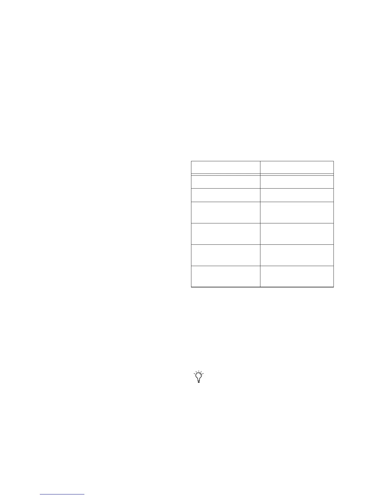
When synchronized to Word Clock, External
Clock input and output do not have to be at the
Word Clock rate. EXT CLOCK IN synchroniza-
tion will typically be 1x the current session sample
rate. However, for sample rates higher than 48
kHz, HD I/O generates a choice of 1x, 2x, or 4x of
a base rate of 44.1 kHz or 48 kHz, as
follows:
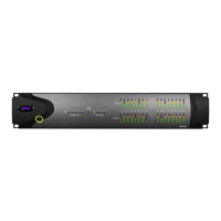
Meters
These four-segment LEDs indicate signal level for
each of the sixteen channels. The top row of meters
indicates input levels, and the bottom row shows
output levels. These meters are calibrated at –42
dB, –18 dB, –6 dB, and 0 dB,
respectively.
Session Sample Rate Word Clock Support
44.1 kHz 44.1 kHz
48 kHz 48 kHz
88.2 kHz 88.2 kHz
44.1 kHz
96 kHz 96 kHz
48 kHz
176.4 kHz 176.4 kHz
44.1 kHz
192 kHz 192 kHz
48 kHz
Note that 0 dB is not to be confused with clip-
ping; use the on-screen meters in Pro Tools
to determine whether a signal is clipping.
 Loading...