Do you have a question about the Avid Technology HD I/O and is the answer not in the manual?
Overview of HD I/O features and channel count.
Details on analog converters, sample rates, and limiting circuits.
Details on digital I/O formats, sample rates, and conversion.
Lists all items included with the Pro Tools | HD I/O.
Information on system requirements and compatibility checks.
Instructions for registering the product online.
Information on where to find the hardware warranty details.
Explains the guide's content and refers to other manuals.
Details on the Avid website services and features.
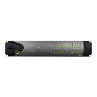
Description of the front panel features and indicators.
Details the back panel layout and connectors for HD I/O.
How to connect HD I/O to HDX hardware.
How to connect HD I/O to HD Native hardware.
How to connect HD I/O to Pro Tools|HD cards.
Accessing the Hardware Setup dialog for configuration.
Steps to set up HD I/O controls in the dialog.
Configuring physical I/O routing and assignments.
Adjusting reference levels and limiters for analog inputs.
Setting digital input formats and sample rate conversion.
Configuring AES/EBU input formats and sample rate conversion.
Configuring ADAT input formats and sample rate conversion.
Configuring TDIF input formats and sample rate conversion.
Information on SRC for digital inputs.
Calibrating input levels using trim pots.
Step-by-step instructions for removing an expansion I/O card.
Step-by-step instructions for installing an expansion I/O card.
Pinout diagram for analog output DB-25 connectors.
Pinout diagram for +4 dBu analog input DB-25 connectors.
Pinout diagram for -10 dBV analog input DB-25 connectors.
Pinout diagram for AES/EBU DB-25 connectors.
Pinout diagram for TDIF DB-25 connectors.
Explains calibration differences between digital and analog devices.
Explanation of headroom concepts for analog and digital signals.
Overview of the analog and digital calibration process.
Step-by-step guide to creating a calibration session in Pro Tools.
Instructions for switching jumpers on analog output cards for level adjustments.
| Channels | 16 |
|---|---|
| Computer Connectivity | DigiLink |
| Bit Depth | 24-bit |
| Connectivity | DigiLink |
| Sample Rates | 44.1, 48, 88.2, 96, 176.4, 192 kHz |
| Sample Rate | 44.1 kHz to 192 kHz |
| Connectors | XLR |
| Compatibility | Pro Tools HD |
| Digital I/O | AES/EBU |
| Converter Type | Analog-to-Digital/Digital-to-Analog |