Pro Tools | HD I/O Guide34
10
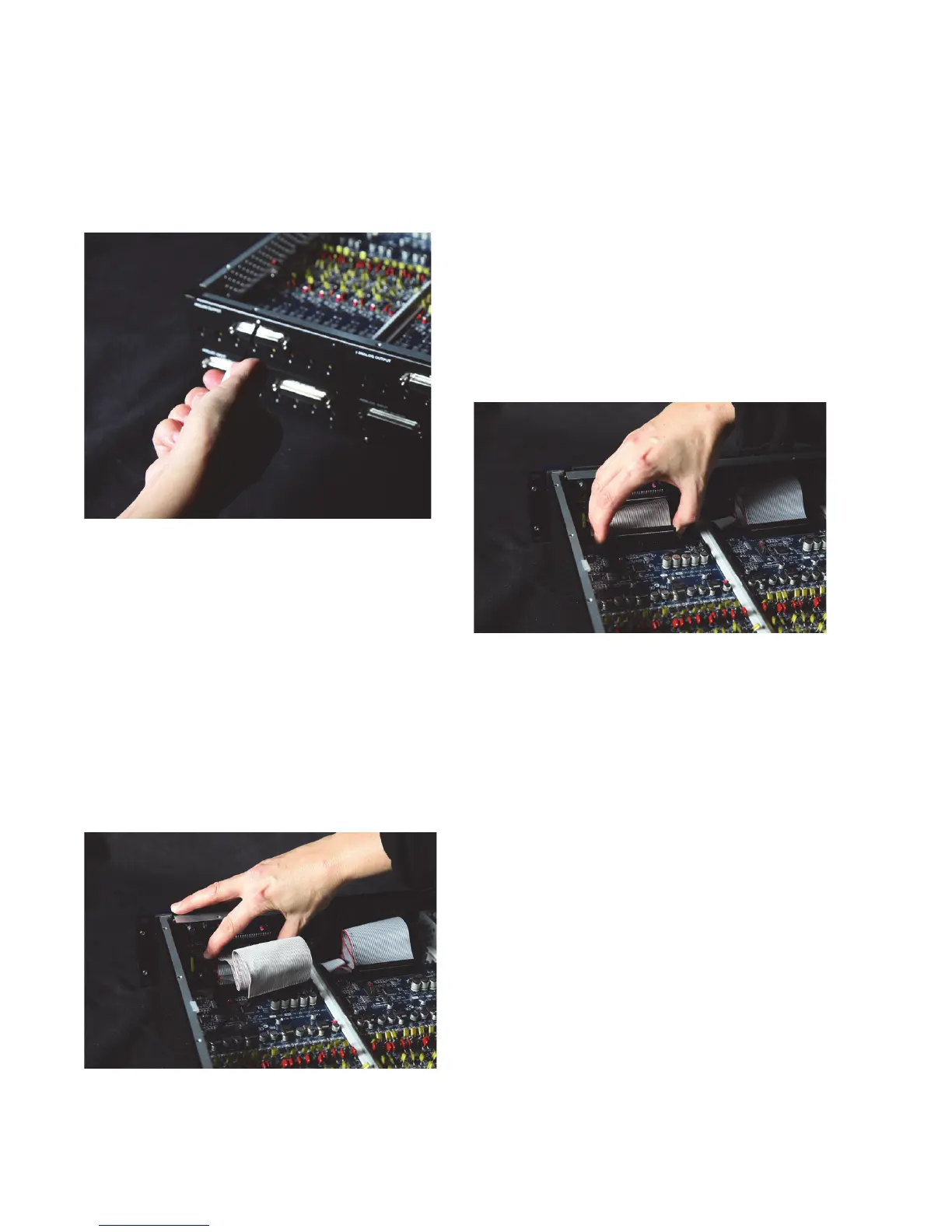
Secure the I/O card to the back panel of the
HD I/O chassis with the same screws you re-
moved from the either the empty bay cover or
from the I/O card you previously removed.
11
Locate the raised ridge in the middle of the con-
nector on one end of the 50-pin cable that con-
nects the I/O card to the HD I/O chassis. This
ridge is only on one side of the connector, and
there is a matching groove on only one side of
the 50-pin connector on the chassis.
12
Gently push the cable connector into the chas-
sis’ connector. The ridge on the cable connector
must line directly into the groove on the chassis
connector. Be very careful not to bend any of
the pins.
13
Locate the raised ridge in the middle of the con-
nector on the other end of the 50-pin cable that
connects the I/O card to the HD I/O chassis.
This ridge is only on one side of the connector,
and there is a matching groove on only one side
of the 50-pin connector on the card.
14
Gently push the cable connector into the card’s
connector. The ridge on the cable connector
must line directly into the groove on the card
connector. Be very careful not to bend any of
the pins or to over-stress the card.
15
Replace the top cover on the HD I/O.
16
Replace the original screws.
17
Reconnect the HD I/O to your system.
18
Power on the HD I/O.
19
When you power on the unit, verify that the
LED ring around the power switch lights or-
ange.
20
Start up the computer.
21
When you start the computer, verify that the
power ring turns from orange to green. (If this
does not occur, see “Troubleshooting” on
page 35.)
22
Launch Pro Tools.
Securing the I/O card to the back panel of the HD I/O
Connecting the 50-pin cable to the HD I/O chassis
Pressing the 50-pin cable connector into the card