EN13EN 12
C - INSTALLATION
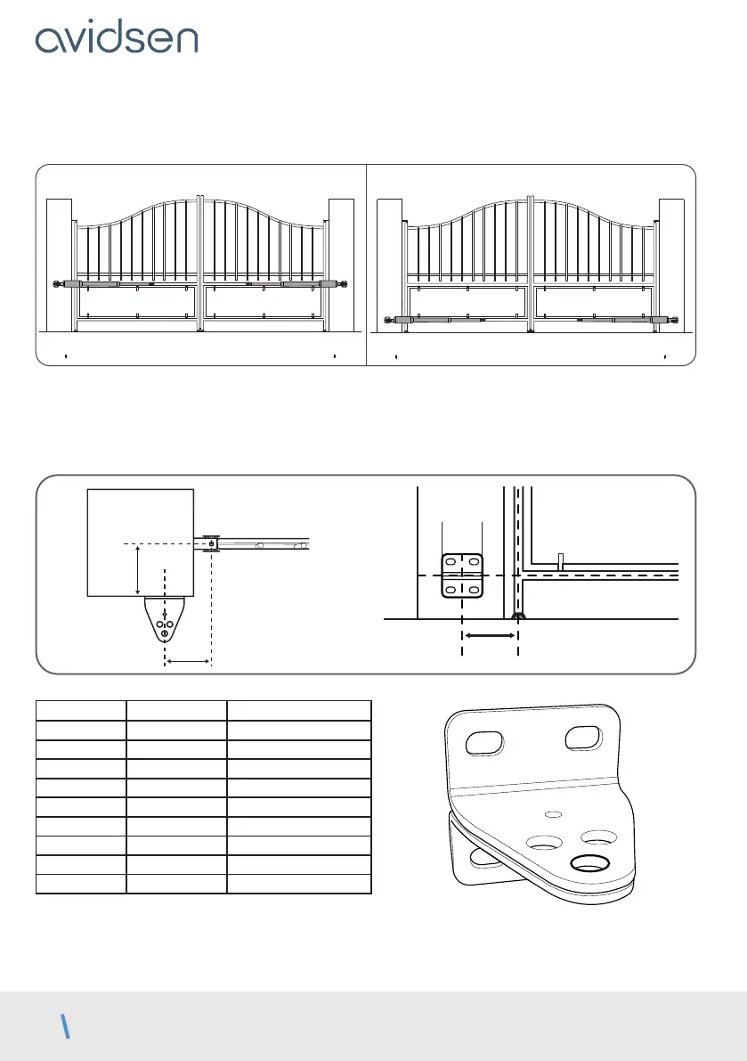
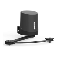
Attaching the post mounting bracket
Mount the motors to a rigid and reinforced part of the gate (e.g. the frame or the crossbar). Mount them as
low as possible for aesthetic and technical reasons.
CORRECT IDEAL
The instructions below describe installation of the left motor; to install the right motor, repeat the process while
respecting the symmetry.
• Measure distance D, then refer to the table for distance B, which allows you to determine the post mounting
bracket position. The table also indicates the hole in which the motor will be mounted.
• The height of the centre of the mounting bracket must be the same as the centre of the gate frame on which
the motor is mounted.
70
mm
D
B
post
D (mm) B (mm) max angle (°)
0
220 120°
30 220 120°
60 210 110°
90 190 110°
120 190 105°
140 180 100°
160 170 95°
180 160 90°
190 160 90°
Mark the location of the holes in the post, ensuring that the post mounting bracket is mounted horizontally at
the end. Use 10-inch lag screws or any other fastening system suitable for the post material.