web-based user interface. For more information, see the DSView 3 Installer/User Guide.
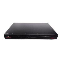
Figure 1.1: Example DSR 2035/8035 Switch Configuration
Table 1.1: Descriptions for Figure 1.1
Number Description Number Description
1 CAT 5 Connection 6 Telephone Network
2 KVM Connection to the Switch 7 Ethernet
3 Remote IP Connection 8 DSView 3 Software Server
4 DSR Switch 9 Analog User (OSCAR
®
Graphical User Interface)
5 Modem 10 Digital User (Computer with Internet browser)
Chapter 1: Product Overview 3