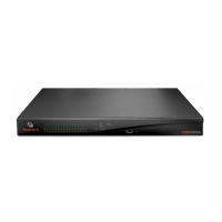
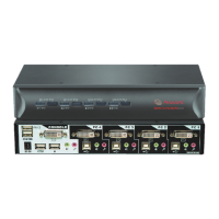
Table 2.1: Descriptions for Figure 2.1
Number
Description
Number Description
1 Digital User 8 Power Cord
2
Telephone
Network
9 Ports 1-32
3 Network 10 Local USB Connections
4 Modem 11 Power Control Device*
5 Analog User 12 Target Devices 1-32
6
External Virtual
Media
13
IQ Modules (PS/2, USB**, VMC***, Sun and serial adaptors are
available)
7 DSR 8035 Switch
*If you are using a PM Intelligent Power Distribution Unit (IPDU), use the provided adapter.**To open a virtual
media session with a target device, the target device must first be connected to the switch using a virtual media-
capable IQ module (USB2 or USB2L).***To use a smart card reader with a target device, the target device must
first be connected to the switch using a smart card capable IQ module (VMC).
Getting started
Before installing your DSR switch, refer to the following lists to ensure you have all items that
shipped with the DSR switch, as well as other items necessary for proper installation.
NOTE: While it is possible to use two DSR switches in a cascaded configuration, it can cause function conflicts and
limit the advanced features of the switch. As a result, Avocent does not recommend this configuration.
Supplied with the DSR switch
• Local country power cord(s)
NOTE: DSR switches equipped with dual power supplies (DSR 2035DAC/8035DAC models) are supplied with two
power cords. All other DSR switch models come with one power cord.
• Rack mounting brackets (depending on switch model)
• Rack Mounting Bracket Quick Installation Guide (depending on switch model)
• DSR Switch Quick Installation Guide
• Either of the following:
• Two ribbon cables with RJ-45 connectors at each end
One RJ-45 to DB-9 (male) adaptor for the modem connection
Chapter 2: Installation 7