AXIS HOV Housing VT Page 7
ENGLISH
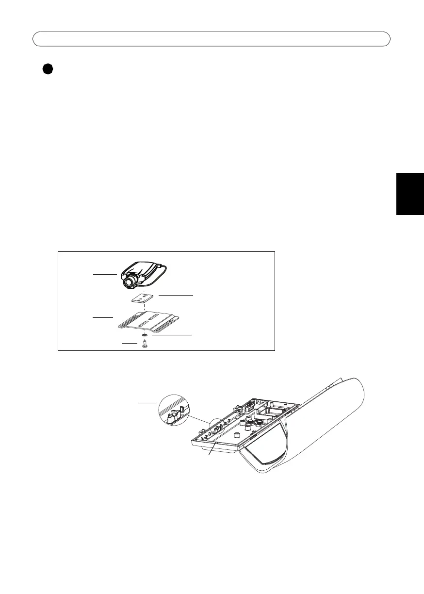
Install the camera in the housing
1. The housing is shipped with 3 black plastic spacers. Use one, two or three spacers
between the camera and holder and make sure that the camera lens is positioned more
than 2mm above the heater and that the cables are not in contact with the heater:
• AXIS 210/210A - 2 spacers
• AXIS 211/211A/211M/211W - 2 spacers
• AXIS 221/223M - 1 spacer
2. Secure the camera, spacer(s) and holder with one of the three screws (flathead) and clear
plastic spacer (fig.2).
3. Fit the slots on the holder to the positioning screws (fig.3).
4. The camera should be positioned so the lens is 1-2mm from the housing window. Slide
the holder to a suitable position and tighten the positioning screws when satisfied.
Positioning
screws for
holder
Heater
positioned here
Clear plastic spacer
Rectangular
spacer(s)
Holder
Axis Network
Camera
Flathead screw
FIG.2
FIG.3