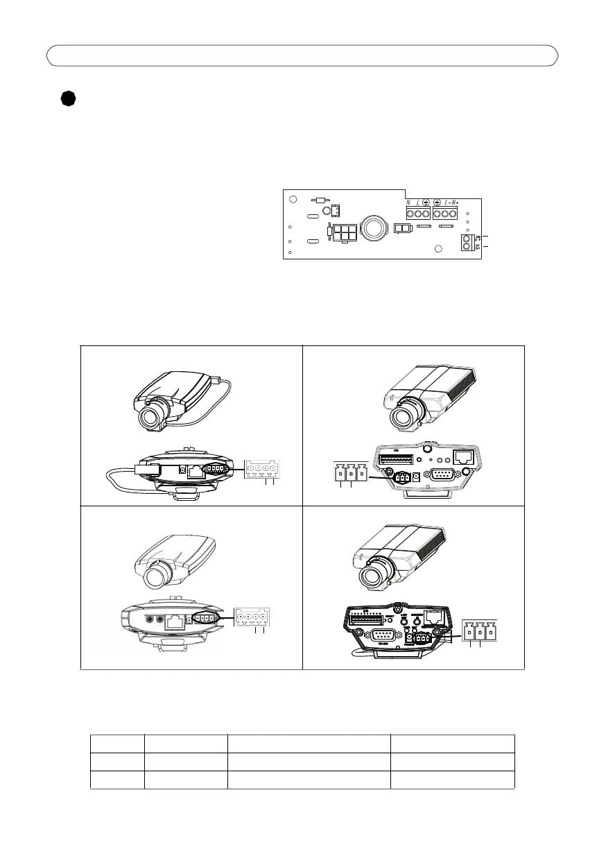
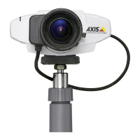
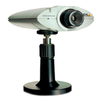
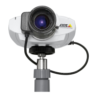
Page 8 AXIS HOV Housing VT
Connect the power cable to the camera
1. Using the small flathead screw driver, loosen the screws in the Power to camera
connector on the connector board (fig.4).
2. Insert the red (+) and black (GND)
wires in the connector and tighten
the screws to secure the wires.
3. Connect the wires to the green
terminal connector on the Axis
network camera (fig.5).
Note: The camera models have different terminal connectors, be sure to follow the correct
description for the installed camera.
Red/black power cable
FIG. 5
AXIS 211/211A/211M/211W AXIS 221
AXIS 210/210A AXIS 223M
+ / GND Wire Connector board Camera
+ Red DC Power (+) Camera DC Power (+)
GND Black GND Camera (GND)
RS-232
RESET
NETWORK / POWER
POWER
PWR
NET
ACAC
DC+
GND
12345678910