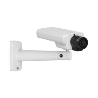
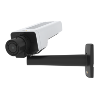
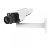
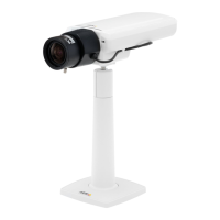
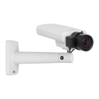
AXIS P1344 Network Camera
Hardware overview
Connectors
Network connector - RJ-45 Ethernet connector. Supports P ower over Ethernet (PoE).
Caution
To protect the product against power surges, a shielded network cable (STP) must be used between the product and the
network switch. Ensure that the network switch is properly grounded.
Audio in (pink) - 3.5 mm input for a mono microphone, or a line-in mono signal (left channel is used from a stereo signal).
Audio out (green) - 3.5 mm output for audio (line level) that can be connected to a public address (PA) s ystem or an active speaker
with a built-in amplifier. A stereo connector must be used for the audio out.
SD card slot - A standard or high-capacity SD card (not included) can be used for l ocal recording with r emovable storage. For
instructions on how to insert and remove an SD card, please refer to the Installation Guide.
Note
Before removal, the SD card should be unmounted to prevent corruption of recordings. To unmount the SD card, go to Setup
>SystemOptions>Storage>SDCardand click Unmount.
Control button - The control button is used for:
• Enabling the Focus Assistant. Press and very quickly release the Control button.
• ConnectingtoanAXISVideoHostingSystemservice.Seepage 41. To connect, press and hold the button for about
1 second until the Status LED flashes green.
• ConnectingtoAXISInternetDynamicDNSService. Seepage 41. To connect, press and hold the button for
about 3 seconds.
• Resetting the product to factory default settings. See page 47.
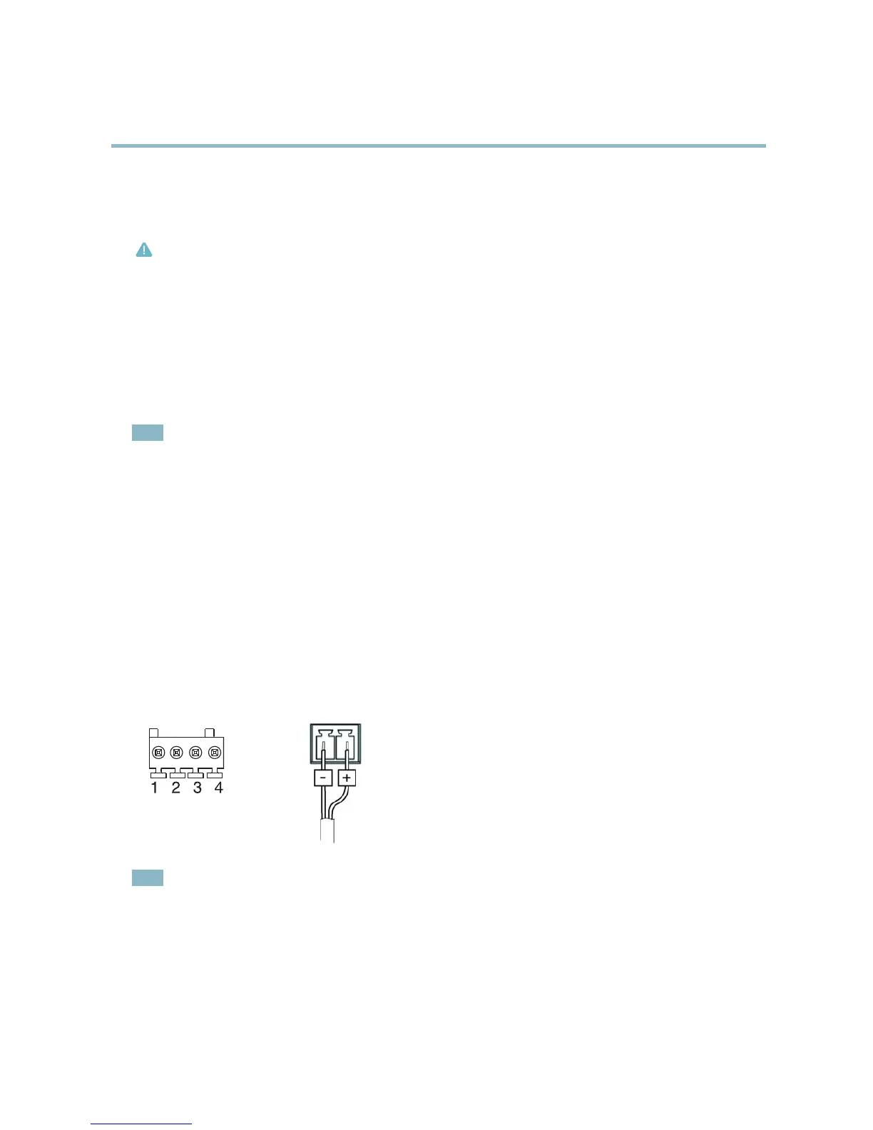
Power connector - 2-pin terminal block for power input.
I/O connector
DC power input
Note
For technical specific
ations, see page 54.
I/O terminal connector - Use in applications for e.g . motion detection, event triggering, time lapse recording and alarm notifications.
In addition to an auxili ary power and a GND pin, the I/O terminal connector provides the interface to:
• Digital output
— For connecting external devices such as relays and LEDs. Connected devices can be activated by
the VAPIX® Application Programming Interface, output buttons on the Live View page or by an Action Rule. The
output will show as active (shown under System Options > Ports & Devices) if the alarm device is activated.
6