1-2
Chapter 1. OVERVIEW
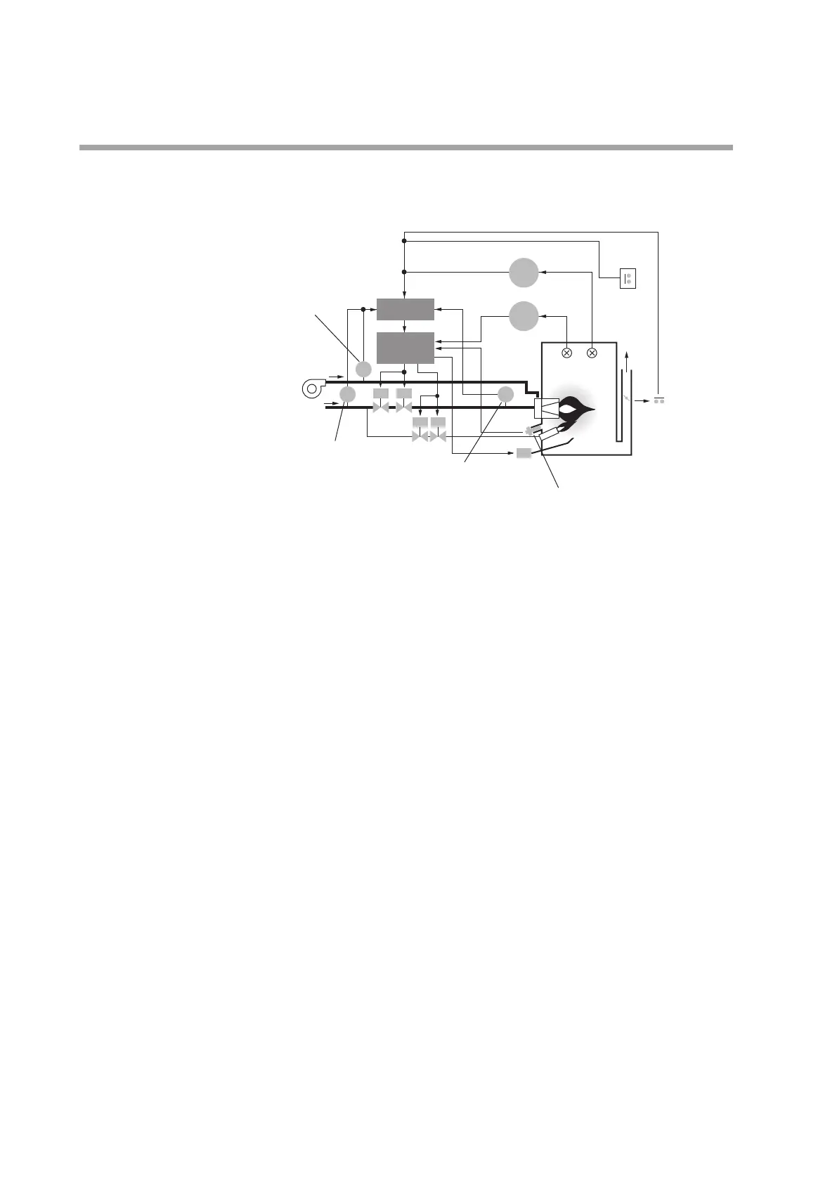
System structure
This device is used to control the flame of combustion equipment, and is used in a
system like the one shown below.
interlock
Gas pressure lower limit
interlock
Gas pressure upper limit
interlock
Ignition
transformer
Air
Gas
MV1 MV2
PV1 PV2
T/C T/C
L
L
H
UV
Controller
Overtemperature limit
Vibration
detection limit
Combustion
chamber
Combustion
equipment
interlock
Flue
duct
Burner controller
BC
(AUR450C)
Limit/Interlock
PS
PS
IG
PS
TIC
TIA
Flame
Exhaust
gas
Vibration
detector
Safety assurance functions
This device performs functions that are vital for burner operation and flame
monitoring.
•
Combustion monitoring and safety shutdown
•
Detects burner flame failure and shuts down the fuel supply immediately.
•
In case of ignition failure or flame failure, shut down each value ignition trans-
former in a predetermined sequence.
•
Startup, operation and shutdown of combustion equipment
•
Operates each value ignition transformer in a predetermined order, with preset
timing.
•
Fixed ignition timing
To ensure safety, the ignition circuit is so designed that ignition cannot continue
in excess of the specified time, even if part of the ignition circuit fails.
•
Safe startup
•
Checks flame detector and flame circuit for internal failure before every startup.
•
If failure is detected, prevents burner startup.
•
Checks for false flame detection or false discharge of the tube unit, failure of
the ignition circuit, and failure of the alarm circuit.
•
Flame safeguard control in compliance with safety standards
This controller’s design is based on North American and European safety stan-
dards, and it is certified to meet them. This device can be used with combustion
safety equipment in Europe and North America.
•
Dynamic self-checking
Checks continuously for sensor failure of the AUD300C/500C and for failure of
the flame detection circuit, even during the RUN stage of operation. If failure is
detected, fuel supply shutdown and lockout are immediately carried out.
•
Protection against part failure
Failure Mode Effect Analysis (FMEA) has been done for all parts. Even if a part
failure occurs, safety will be maintained, and dangerous conditions such as the
following will not occur:
•
Out-of-order ignition sequence.
•
Dangerous sequence timing (longer ignition time)