2-1
Chapter 2. NAMES AND FUNCTIONS OF PARTS
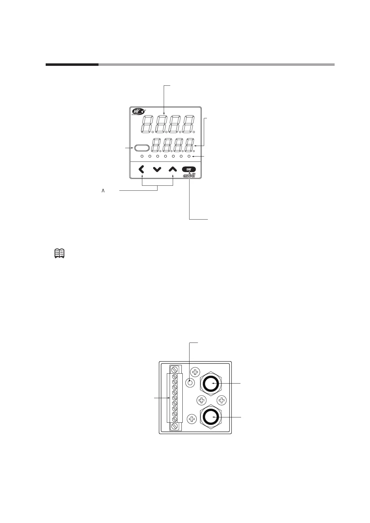
Display
L
OK
SP1 SP2 SP3 EV1 EV2
DISP
PV
SP
ENT
Upper display: Displays the instantaneous flowrate value
(7-segment display).
When the display is switched, it also displays the
integrated flowrate value (upper 4 digits),
parameter setup item, function setup item or alarm details.
Lower display: Displays the set flowrate
(7-segment display).
When the display is switched, it also
displays the operation mode,
integrated flowrate values (lower 4 digits),
value drive output, parameter setup values,
function setup values.
Operation lamp
L: Indicates that the integrated flowrate is
displayed.
Flashes when an integration event occurs.
OK: Lights when the control flowrate is within
the "setting value ± alowable range".
Flashes when the operating mode is valve
fully-open.
SP1 to SP3: The lamp corresponding to the SP No.
which is used at multi-setup is lit.
EV1, EV2: Lights when the event output is ON.
[ENT] key: Used when setting the SP value and storing
the value. It also can be used for the
integrated flowrate resetting and alarm
resetting.
[DISP] key: Used when switching
the details of display.
[<], [V], [ ]keys:
Used when incrementing/decrementing
the digit or moving to a desired digit.
Note
• The definition of the terms used in this manual is as follows:
SP (Set Point): Set flowrate value
PV (Process Variable): Instantaneous flowrate value (control flowrate)
Operation mode: 3 mode of "valve fully-closed / valve control / valve fully-
open"
Rear view
Pipe connection outlet port:
This is the out flow side port.
Pipe connection inlet port:
This is the in flow side port.
Connector:
1 2 3 4 5 6 7 8 9
Loader jack:
Connects to a personal computer by
using a dedicated loader cable sold separately.