7-5
Chapter 7. SPECIFICATIONS
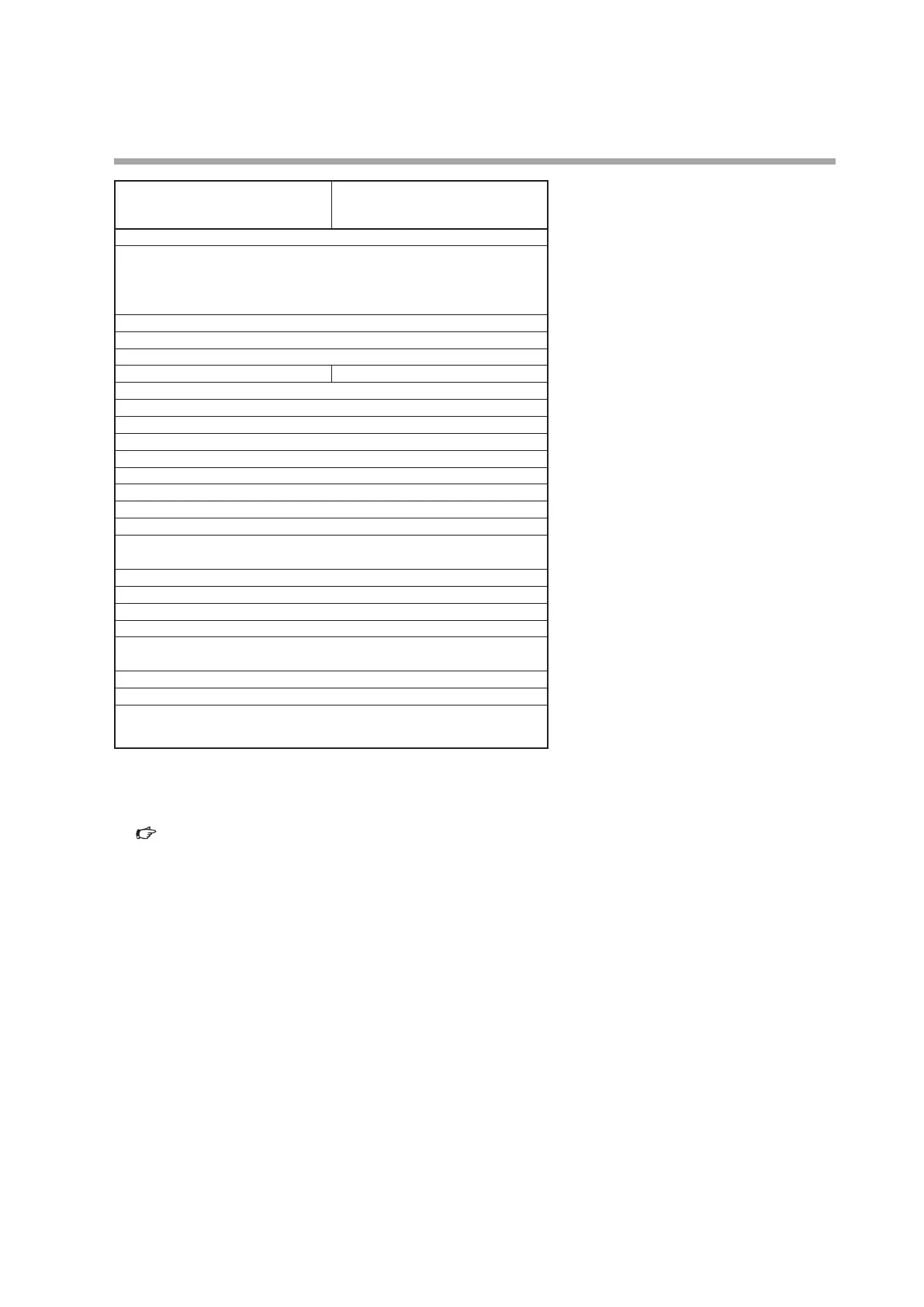
MPC0005 MPC0020
7 V DC max. (maximum output when flowrate exceeds range)
±0.5 % FS
(The input impedance of the connected device must be at least 100 kΩ.)
Total output accuracy: Indication accuracy ±0.5 % FS
2 points
30 V DC 15 mA max. (open collector non-insulated output)
100 ms ±10 % (when the integrated pulse output is selected.)
0.1 L / 1 pulse 1 L / 1 pulse
2 points
Non-voltage contact or open collector
2.0 ±0.5 V
Approx. 0.5 mA (contact current)
Max. 250 Ω
Min. 100 kΩ
Max. 1.0 V (with open collector)
Max. 50 μA (with open collector)
(1)Loader communication *
5
(2)RS-485 communications(3-wire) *
6
2400, 4800, 9600, 19200, 38400 bps (only 19200 bps for loader
communication)
24 V DC, current consumption 300 mA max.
22.8 to 25.2 V DC (ripple 5 % max.)
Brass(Ni plated), stainless steel, Teflon, Viton
Rc1/8
Display surface must be placed vertically (inlet port: lower side, outlet
port: upper side)
Approx. 300 g
Mounting bracket (81446917-001), wiring connector
EN61326-1: 2013, EN61326-2-3: 2013
During EMC testing, the reading or output may fluctuate by ±20 % FS.
*2 Differential pressure required for obtaining full-scale flowrate.
*3 Operation is possible even under the required differential pressure. However, the controllable flowrate range will become
small. For details, refer to;
Relationship between flowrate and differential pressure with valve fully opened (in air) (next page).
*4 Applicable only to the model with analog input/output function.
*5 The MLP200A100 Loader Package (sold separately) for the MPC is required.
*6 Applicable only to the model with RS-485 communications function.